Storage system having transaction monitoring capability

a storage system and transaction monitoring technology, applied in the field of storage systems, can solve the problems of file-level system only being applied to specific applications and platforms, no backup schedule, file-level solution across all platforms,

Inactive Publication Date: 2007-12-27
HITACHI LTD
View PDF11 Cites 104 Cited by
  • Summary
  • Abstract
  • Description
  • Claims
  • Application Information

AI Technical Summary

Problems solved by technology

Traditional data backup systems are only able to restore data to certain discrete points in time at which backups were made, such as one hour, one day, one week, etc.
However, with continuous data protection, there are no backup schedules.
Furthermore, there is no common file-level solution across all platforms, so file-level systems can only be applied to specific applications and platforms.
Furthermore, if the storage system becomes contaminated with a virus, or if a file in the system is corrupted or accidentally deleted, and the problem is not discovered until some time later, a user is still able to recover the most recent uncorrupted version of the file.
If the money is dispensed without debiting the customer's account, the bank loses the money.
Because each type of transaction is a concept defined specifically within each application program, that is, within a host computer or a set of host computers where each of the application programs run, storage systems are usually unable to distinguish whether an I / O operation is the start, middle or end of a transaction for a particular application program.
Therefore even when storage systems have the capability of recovering data at each I / O, such as through CDP, the recovered data might be useless unless the data is recovered according to its state at the end of a transaction or at the beginning of a transaction.
However, none of these applications disclose how to manage a transaction that is composed of a plurality of requests or actions by a plurality of application programs.
However, in an environment where one or more host computers exist and multiple application programs are running, storage systems usually do not know which I / O operation is the start or end of the transaction for the application programs.

Method used


Image

  • Storage system having transaction monitoring capability
  • Storage system having transaction monitoring capability
  • Storage system having transaction monitoring capability

Examples


first embodiment

tion

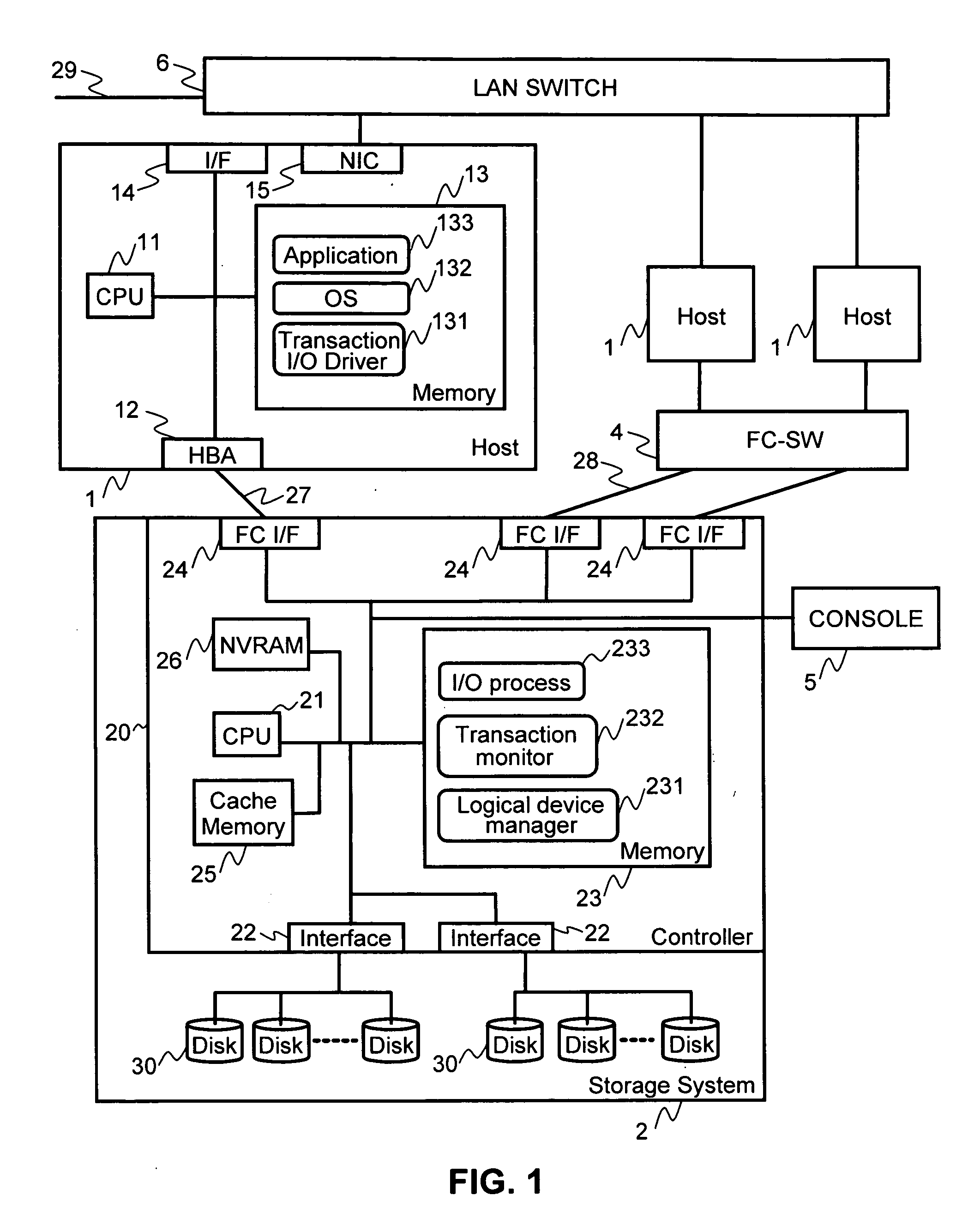
[0040]FIG. 1 illustrates an example of the system in which the method and apparatus of this invention may be applied. The system is composed of one or more host computers 1 (hereinafter referred to as “host 1”), and a storage system 2. Hosts 1 may be connected for communication with storage system 2 via a direct connection 27 or via a Fibre Channel (FC) switch (FC-SW) 4 as part of a storage area network 28. Further, hosts 1 may be able to communicate with each other via a local area network (LAN) 29 including a LAN switch 6. The physical interface of LAN switch 6 is Ethernet in this embodiment, but may be other types of networking protocols as well.

[0041]Host 1 may be a PC / AT compatible computer or workstation that runs a UNIX® or Windows® operating system. In another embodiment, host 1 may be a mainframe computer running IBM's OS / 390® or z / OS® operating systems. Host 1 is composed of at least a CPU 11, a memory 13, a Network Interface Controller (NIC) 14, and a HBA (host bus ad...

second embodiment

[0131]The hardware and software configuration in the second embodiment is the same as described above with respect to the first embodiment. The difference of the second embodiment from the first embodiment is in the management method of each transaction and the usage of transaction APIs, as follows:

[0132]int RequestTransaction(char **DEVLIST): When AP 133 calls the RequestTransaction function, the storage system 2 returns a transaction number defined in the storage system 2, as described above with respect to the first embodiment. The process of calling of the RequestTransaction function by AP 133 and the response of the storage system 2 are the same for the second embodiment as was described above in the first embodiment, such as in FIG. 9.

[0133]int open(const char *pathname, int flags): Instead of the TP_Open function 702 described above, the standard C-programming system call is used for the second embodiment.

[0134]off_t Iseek(int fd, off_t offset, int whence): Instead of TP_Lsee...

third embodiment

[0148]From the foregoing, it will be apparent that the present invention is useful for information systems where a plurality of application programs work cooperatively, and is especially is useful when recovering data in a consistent state at the beginning of, or at the end of a transaction in the application programs. As a third exemplary embodiment, FIG. 15 illustrates an example of how a plurality of application programs can work together using the technology of the present invention.

[0149]The system configuration in the third embodiment is similar to that of the first and second embodiments, except that a secondary storage system 2-2 is connected to a primary storage system 2-1. The hardware configuration of the primary storage system 2-1 and secondary storage system 2-2 may be the same as that of the storage system 2 described above in the first embodiment. However, an additional link 7 may be provided for copying data directly from the primary storage system 2-1 to the seconda...


PUM


Abstract

A system and method for managing transactions of application programs at a storage system enables data protection on a per-transaction basis. The storage system receives an instruction indicating a beginning of a transaction, and determines at least one primary volume for receiving data for the transaction. The storage system also provides a log volume for initially storing write data designated for the primary volume associated with the transaction. When the transaction is successfully completed the data stored in the log volume for the transaction is applied to the primary volume.

Description

BACKGROUND OF THE INVENTION[0001]1. Field of the Invention[0002]The present invention relates generally to storage systems, and, more particularly, to a method for simultaneously handling a plurality of data access requests while enabling data protection.[0003]2. Description of Related Art[0004]Continuous Data Protection (CDP)[0005]Continuous data protection (CDP) provides a storage system in which the data is backed up whenever any change is made to the data. Continuous data protection is different from traditional data backup in that it is not necessary for a user to specify the point in time at which the user would like to recover data until the user is actually ready to perform a restore operation. Traditional data backup systems are only able to restore data to certain discrete points in time at which backups were made, such as one hour, one day, one week, etc. However, with continuous data protection, there are no backup schedules. Rather, when data is written to disk, it is a...

Claims


Application Information

Patent Timeline
Patent Type & Authority Applications(United States)
IPC IPC(8): G06F12/16G06F12/14
CPCG06F11/1474G06F11/1471
Inventor KITAMURA, MANABU
Owner HITACHI LTD
Why Eureka
Try Eureka