System and method for exhaust recirculation

a technology of exhaust and recirculation, which is applied in the direction of machines/engines, mechanical equipment, electric control, etc., can solve the problems of all the cylinders of the engine being subject to backpressure, power supplied to the turbocharger assembly may decrease, and energy, in the form of heat, may be los

Inactive Publication Date: 2008-01-03
CATERPILLAR INC
View PDF29 Cites 42 Cited by
  • Summary
  • Abstract
  • Description
  • Claims
  • Application Information

AI Technical Summary

Problems solved by technology

However, in an engine that also includes a turbocharger assembly powered by engine exhaust, the power supplied to the turbocharger assembly may decrease as exhaust is directed away from the turbocharger assembly and towards the intake air supply.
Furthermore, energy, in the form of heat, may be lost as the engine exhaust travels towards the intake manifold.
However, in Brookshire, all of the engine's cylinders may be subject to backpressure associated with the exhaust recirculation system.
The backpressure may negatively affect the efficiency of the engine, and may result in reduced performance.

Method used


Image

  • System and method for exhaust recirculation
  • System and method for exhaust recirculation
  • System and method for exhaust recirculation

Examples


Embodiment Construction

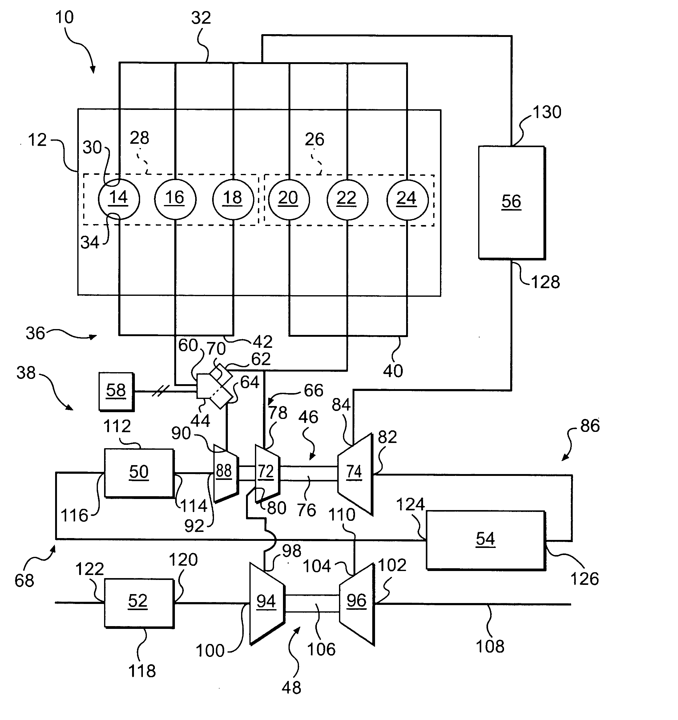
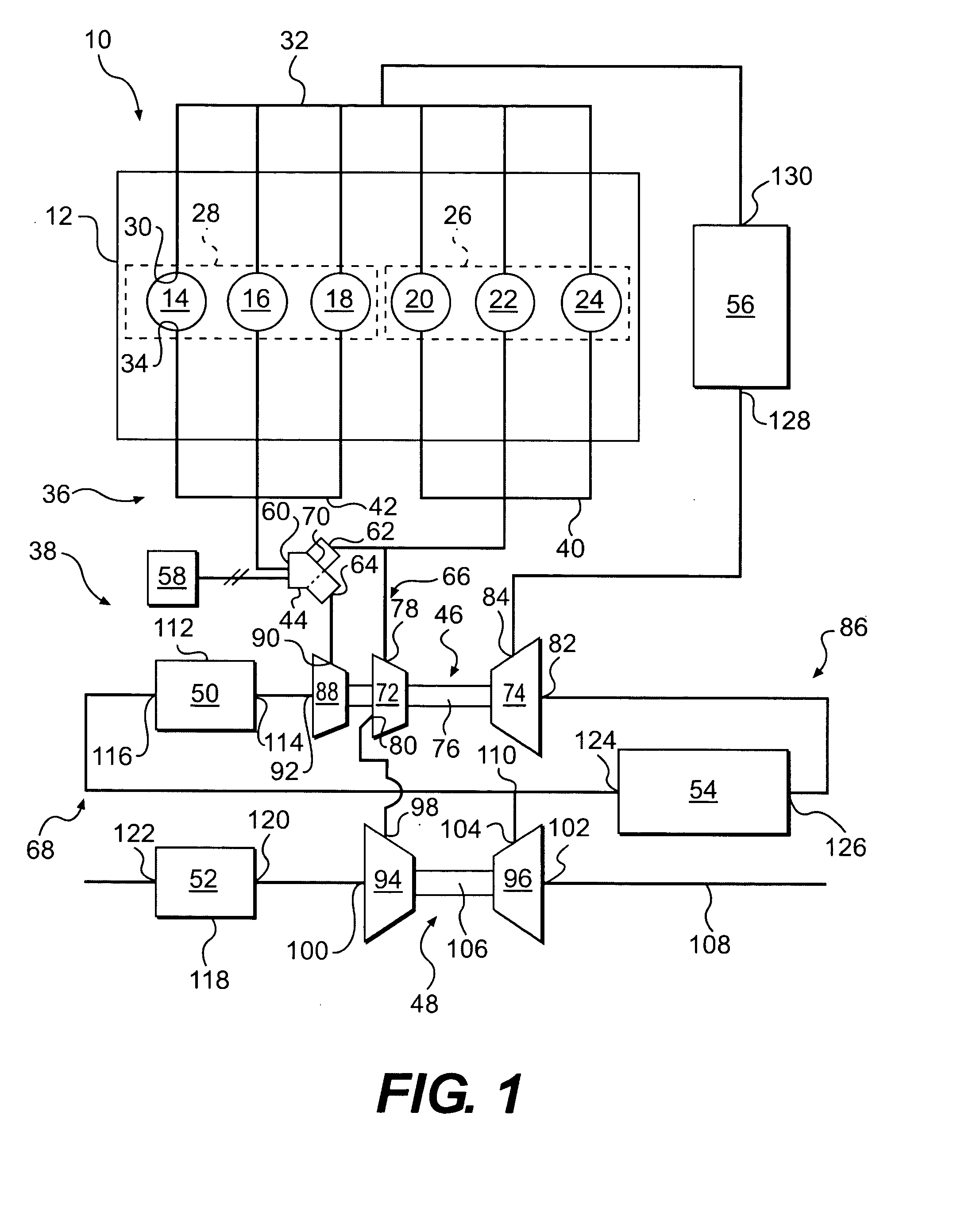
[0020]FIG. 1 illustrates an exemplary engine assembly 10 for a powered system or machine (not shown). Engine assembly 10 may include, among other things, a power source. In one embodiment, the power source may include an internal combustion engine 12, such as, for example, a diesel engine, a gasoline engine, a gaseous fuel-powered engine, and the like, or any other engine apparent to one skilled in the art.

[0021]Engine 12 may include combustion cylinders 14, 16, 18, 20, 22, and 24. Combustion cylinders 14, 16, 18, 20, 22, and 24 may be divided into a first cylinder group 26 and a second cylinder group 28. It should be understood that while six cylinders are shown in the drawings, engine 12 may include three, six, eight, ten, twelve, or any other suitable number of combustion cylinders. Each of cylinder groups 26 and 28 may include, for example, half of the total number of combustion cylinders 14, 16, 18, 20, 22, and 24. In the embodiment shown, combustion cylinders 20, 22, and 24 ma...


PUM


Abstract

An engine assembly may include an engine having a plurality of combustion cylinders, and an exhaust manifold configured to receive exhaust from the plurality of combustion cylinders. The exhaust manifold may be divided into first and second sections. The first section may be fluidly coupled to a first group of combustion cylinders, and the second section may be fluidly coupled to a second group of combustion cylinders. The engine assembly may also include a turbocharger having an exhaust turbine configured to receive exhaust from the first section. The engine assembly may further include a proportional valve assembly configured to selectively fluidly couple the second section to at least one of the turbocharger and an exhaust recirculation loop.

Description

U.S. GOVERNMENT RIGHTS[0001]This invention was made with government support under the terms of DE-FC05-00OR22806 awarded by the Department of Energy. The government may have certain rights in this invention.TECHNICAL FIELD[0002]The present disclosure relates generally to a system for recirculating exhaust, and more particularly, to a turbocharged system for recirculating exhaust in an engine assembly.BACKGROUND[0003]Engines, including diesel engines, gasoline engines, gaseous fuel-driven engines, and other engines known in the art, may exhaust a complex mixture of air pollutants. The air pollutants may be composed of gaseous and solid material, including particulate matter, nitrogen oxides (NOx), and sulfur compounds.[0004]Due to heightened environmental concerns, exhaust emission standards have become increasingly stringent over the years. The amount of pollutants emitted from an engine may be regulated depending on the type, size, and / or class of engine. One method that has been i...

Claims


Application Information

Patent Timeline
Patent Type & Authority Applications(United States)
IPC IPC(8): F01N5/04F01N3/10F02B33/44
CPCF02B29/0412F02D41/0065F02M25/0711F02M25/0712F02M25/0719Y02T10/47F02M25/074F02M25/0748F02M25/0796Y02T10/146F02M25/0739F02M26/16F02M26/08F02M26/09F02M26/34F02M26/35F02M26/42F02M26/71Y02T10/12Y02T10/40
Inventor KIESER, ANDREW J.
Owner CATERPILLAR INC
Why Eureka
Try Eureka