
Respiratory therapy apparatus with oxygen flow diverter

a technology of diverter and respiratory therapy, which is applied in the direction of respirator, respirator, life-saving device, etc., can solve the problems of delay in necessary emergency nebulizing treatment to a patient, requiring a significant amount of therapist's time, etc., to improve patient safety, improve the efficiency of therapist's time, and improve the effect of patient comfor

Inactive Publication Date: 2008-01-03
DASHER MEDICAL SUPPLY
View PDF7 Cites 32 Cited by
  • Summary
  • Abstract
  • Description
  • Claims
  • Application Information

AI Technical Summary

Benefits of technology

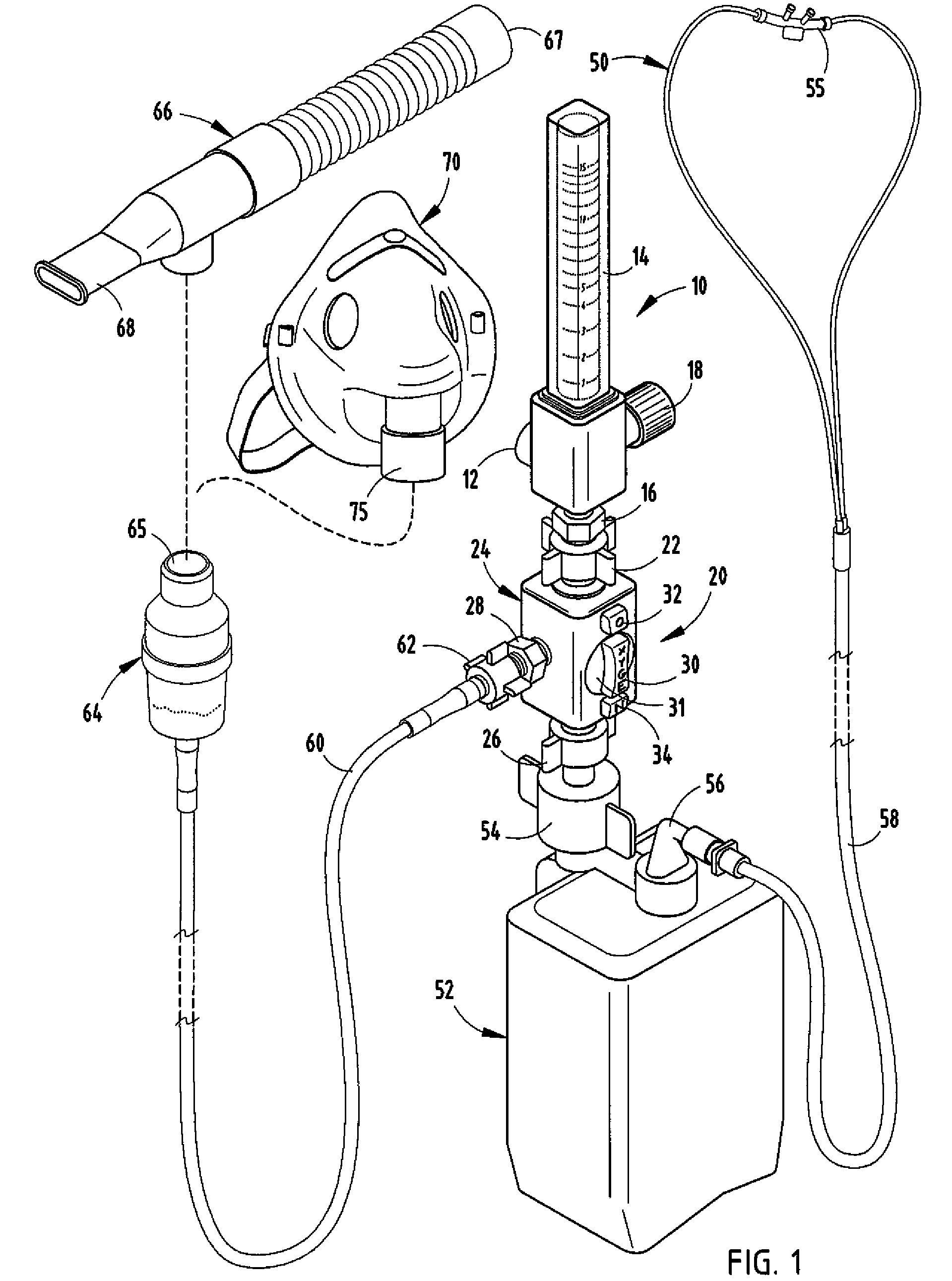
[0006]The system of the present invention overcomes the difficulties of the prior art by providing a treatment apparatus including a three-way diverter valve which has an input adapted to be coupled to the output of an oxygen flowmeter and two outputs which can be sequentially selected utilizing a control handle. The three-way valve has a first output which can be coupled to a cannula or to a cannula through a humidifying container of water which is selected by a first position of the valve. The valve has a second output which, upon rotating the control handle of the valve, diverts the oxygen to the second output to which a nebulizer treatment tube can be coupled, diverting the flow of oxygen from the cannula to the nebulizer treatment tube. Both the cannula and the nebulizer tube may, therefore, be continuously attached to the apparatus and allows the respiratory therapist to easily change from one mode of operation to the other without requiring disconnecting and reconnecting a variety of fittings. This greatly improves the efficiency of the therapist's time and improves patient safety by allowing rapid access to nebulizing treatments if necessary on an acute basis.
[0008]Thus, with the apparatus of the present invention, the respiratory therapist can more efficiently tend to patient care and needs and, as a result, can handle a greater number of patients during a given time period, thereby reducing overall patient cost. Also, patient safety and care is improved by the substantially faster availability of emergency nebulizer treatments.

Problems solved by technology

In view of the fact that numerous treatments are given throughout the day to many patients, the disconnecting and reconnecting of the various tubing requires a significant amount of the therapist's time and, in some cases, can delay necessary emergency nebulizing treatment to a patient.

Method used


Image

  • Respiratory therapy apparatus with oxygen flow diverter
  • Respiratory therapy apparatus with oxygen flow diverter
  • Respiratory therapy apparatus with oxygen flow diverter

Examples


Embodiment Construction

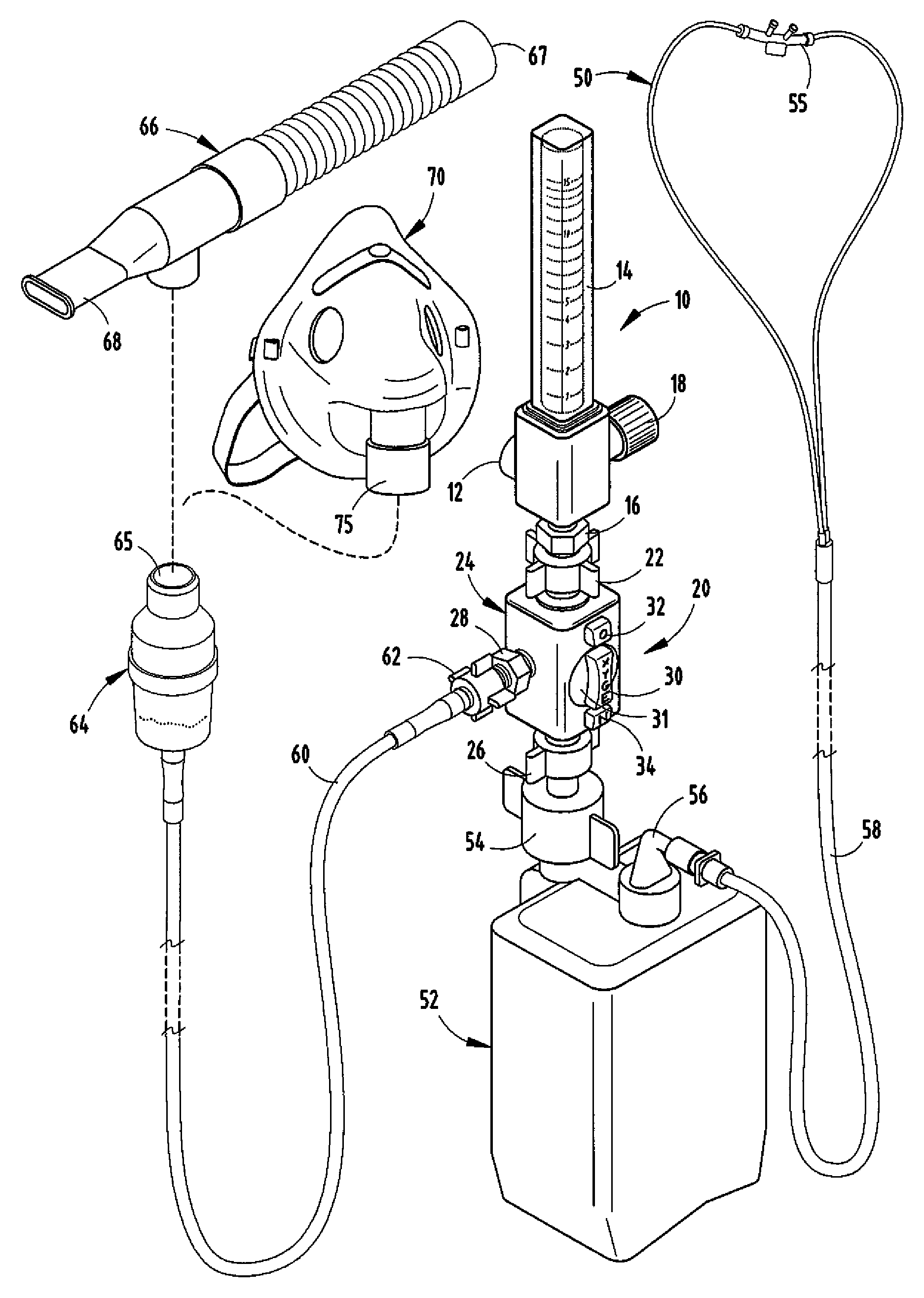
[0014]FIG. 1 shows an installation of the invention in a hospital or other facility in which respiratory treatment is required for patients. The system typically will include a flowmeter 10, which has a rear fitting 12 which attaches to an oxygen outlet in the wall of a facility. The flowmeter includes a ball-type flow gage 14 indicating the liters per minute flow of oxygen at an outlet 16. The flow rate is adjustable by a valve control handle 18 to select the flow rate of oxygen supplied to either a breathing cannula 50 or a nebulizer tube 60 or to shut off the oxygen.

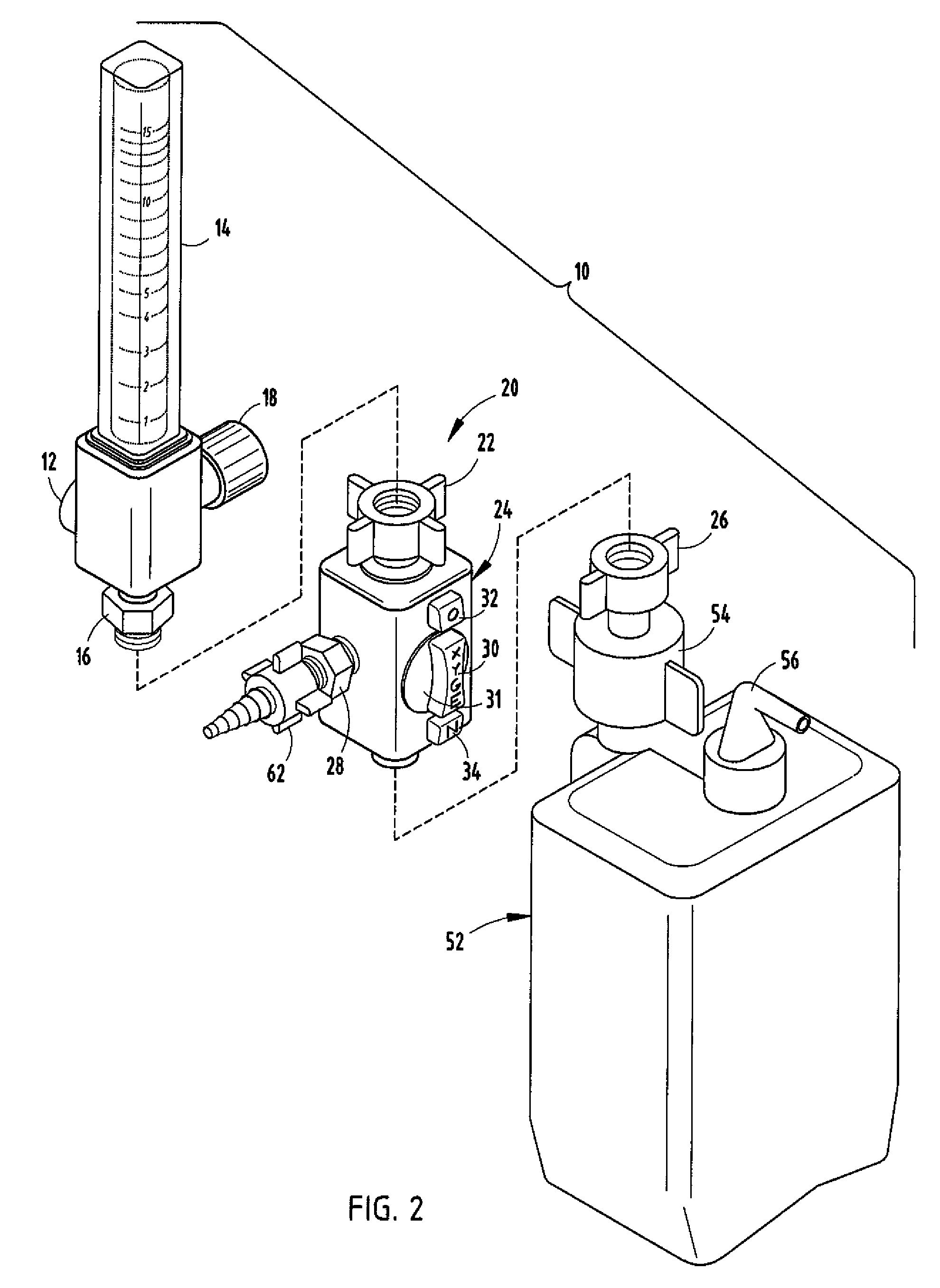
[0015]The outlet 16 of flowmeter 10 includes a threaded end which receives a rotatable, flanged, internally threaded coupling 22 of a flow diverter valve 20 of the present invention. Coupling 22 allows the valve to be sealably attached to the outlet 16 of the flowmeter. Valve 20 includes a valve body 24, an oxygen inlet 25 (FIGS. 3 and 4) to which coupling 22 is threadably secured. Valve 20 also includes a first outle...


PUM


Abstract

A three-way diverter valve has a body with an input with a fitting for securing the input to the output of a flowmeter. The valve body also includes first and second outputs and a ball coupled to a control handle for rotating the ball valve to first or second positions. The ball has a passageway for supplying oxygen to either said first output or said second output. The control handle may include indicia identifying the active flow direction for the selected output.

Description

CROSS-REFERENCE TO RELATED APPLICATIONS[0001]This application claims priority under 35 U.S.C. § 119(e) on U.S. Provisional Application No. 60 / 818,214 entitled OXYGEN FLOW DIVERTER, filed on Jul. 3, 2006, by Nancy Myers Wall, the entire disclosure of which is incorporated herein by reference.BACKGROUND OF THE INVENTION[0002]The present invention relates to an apparatus for use in a hospital for treatment of respiratory diseases and particularly to a system for allowing a therapist to easily treat patients requiring either supplemental oxygen for breathing or for small volume nebulizer treatments without the need for disconnecting and reconnecting various fittings.[0003]Statistics show that the occurrence of respiratory ailments is dramatically increasing in the U.S. population. Such ailments include asthma and chronic obstructive pulmonary disease (COPD), and secondary respiratory problems caused by pneumonia and bronchitis. These maladies frequently require the patient to be hospita...

Claims


Application Information

Patent Timeline
IPC IPC(8): A61M16/20
CPCA61M16/20
Inventor WALL, NANCY
Owner DASHER MEDICAL SUPPLY
Learn More