Water Storage Evaporation Control

a technology of water storage and evaporation control, which is applied in the direction of packaging, buildings, constructions, etc., can solve the problems of high water loss from large open storage due to evaporation, difficult control, and restricted coverage of art devices, etc., and achieves the effect of easy laying on large or small water surface areas

Inactive Publication Date: 2008-01-03
AQUA GUARDIAN GROUP
View PDF7 Cites 25 Cited by
  • Summary
  • Abstract
  • Description
  • Claims
  • Application Information

AI Technical Summary

Benefits of technology

[0024] Although it is possible to link the modules together it is preferred not to have any interconnection between the modules to make manufacture and installation simple. In use the modules will tend to accumulate in an area dictated by the prevailing winds and the area of coverage will depend on the number of modules used. The shape of the individual modules and the movement between them will conserve water storage by limiting the evaporation of the water without interfering with the aqua culture because sufficient area will be exposed to allow oxygenation of the water. It is possible to use ropes or cables to constrain a group of modules to a particular location.
[0025] In a preferred embodiment the upper and lower surfaces are identical with identical openings for water and air ingress and egress. This makes installation easier as the modules don't have to be laid with a particular surface on top. Ideally the modules can be pushed edgewise to the water to hasten the filling with water ballast.
[0026] A baffle may be positioned between the upper and lower surfaces to create two chambers. The upper and lower surfaces may be fluted to strengthen the body and facilitate fluid flow over the surface. Preferably the ridges and valleys of the fluted surface form a multi-point star pattern on the surface which is effective as an omni directional wind lift spoiler.
[0028] In another preferred aspect the modules are designed to allow manufacture on site to avoid the need for transportation from the manufacturing location. Blow moulding or thermoforming is a preferred manufacturing method because blow moulding or thermoforming equipment is able to be moved and set up in temporary facilities on site.
[0029] On site manufacture of the module minimises installation costs.

Problems solved by technology

In regions of high evaporation and seasonal rainfall water loss from large open storages due to evaporation is high and is difficult to control.
These prior art devices are restricted to coverage of limited areas by their inherent: Dynamic inflexibility on the water surface The need for a fixing mechanism between the modules and / or affixing to the perimeter of the water storage The need to be anchored and held down during high winds.
Although the wall depth is large under wave and local high surface wind conditions the covers can be blown off the water surface and overturned.

Method used


Image

  • Water Storage Evaporation Control
  • Water Storage Evaporation Control
  • Water Storage Evaporation Control

Examples


first embodiment

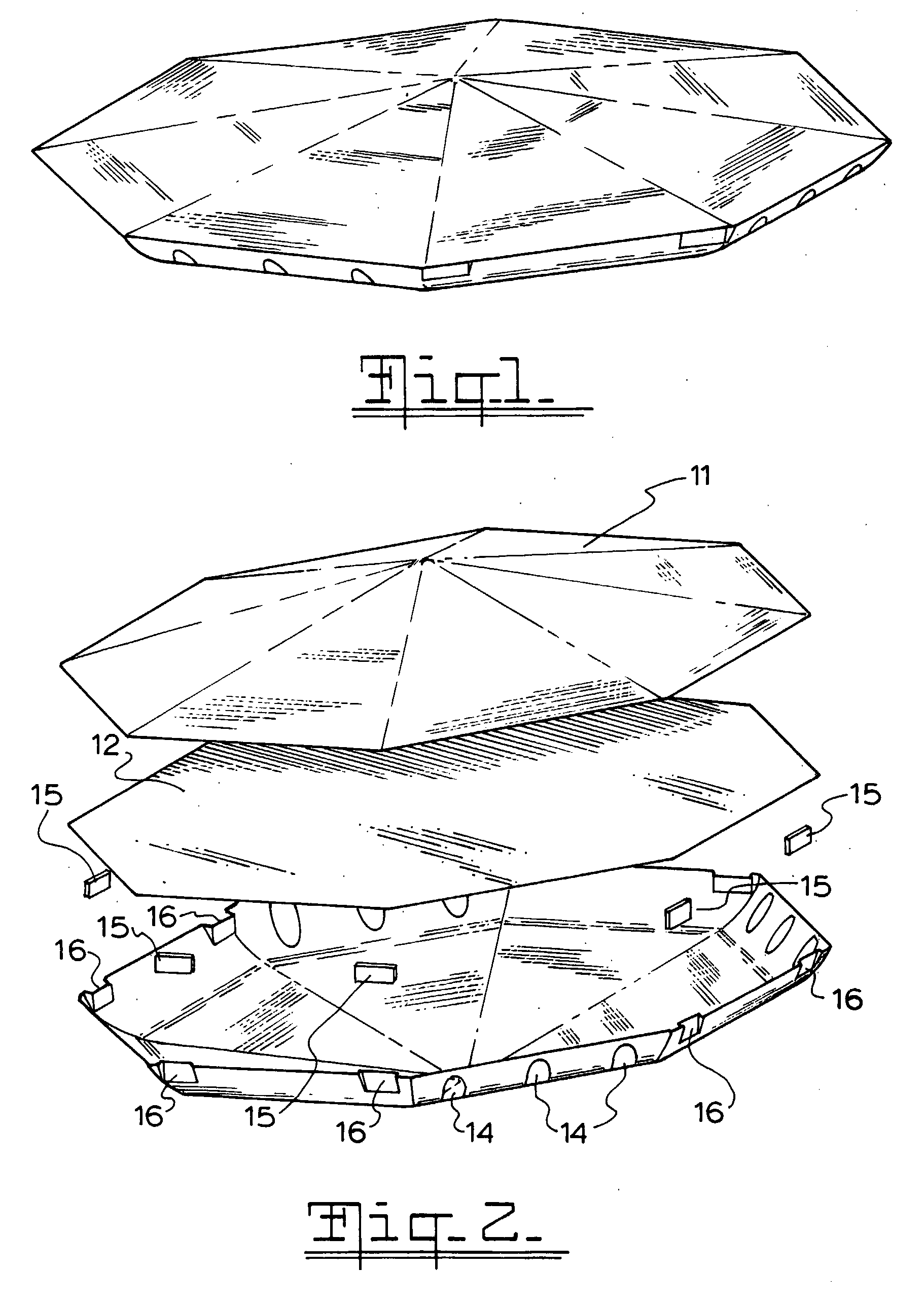
[0035]FIG. 1 is a perspective view of the invention;

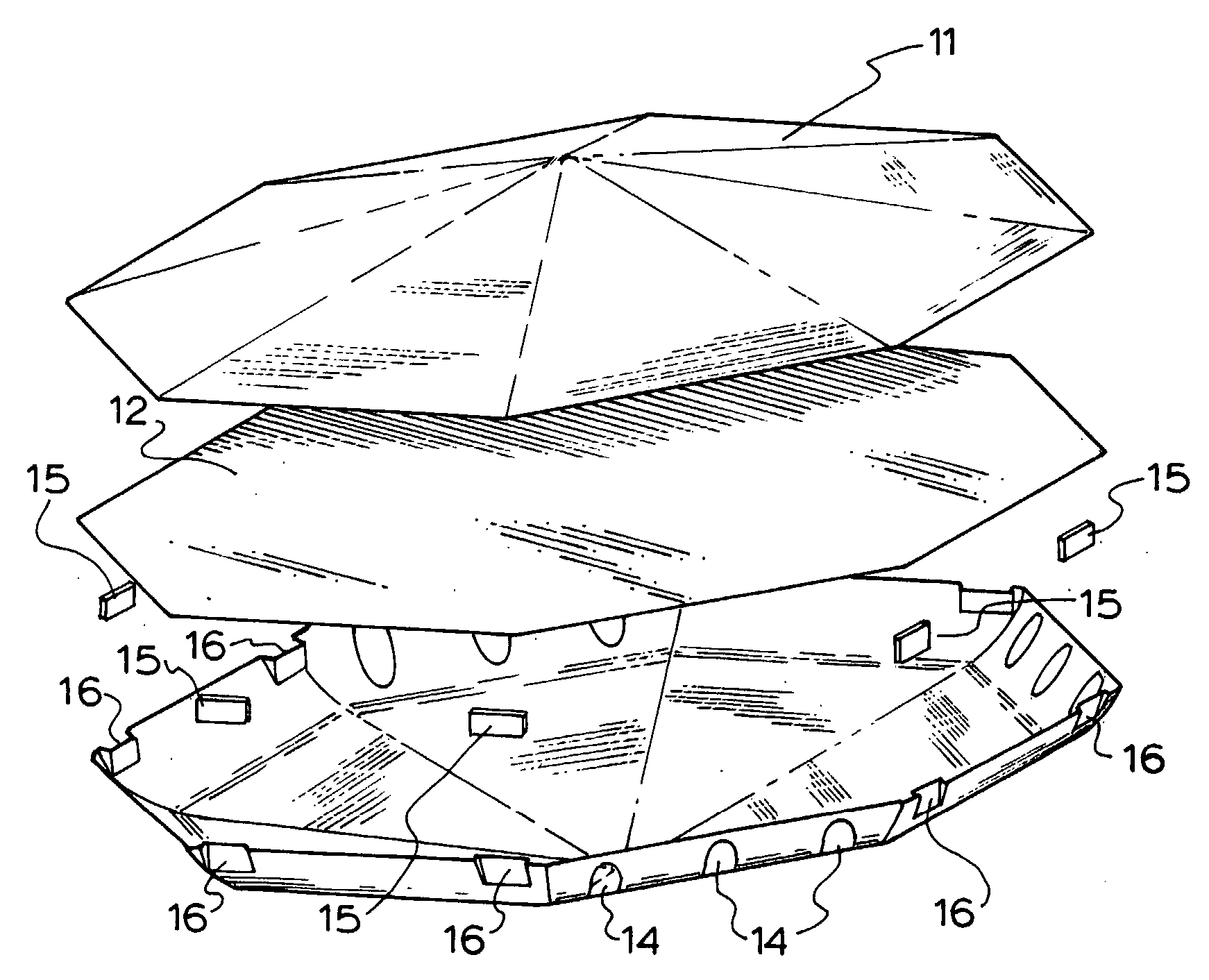
[0036]FIG. 2 is a top perspective of an exploded view of the embodiment of FIG. 1;

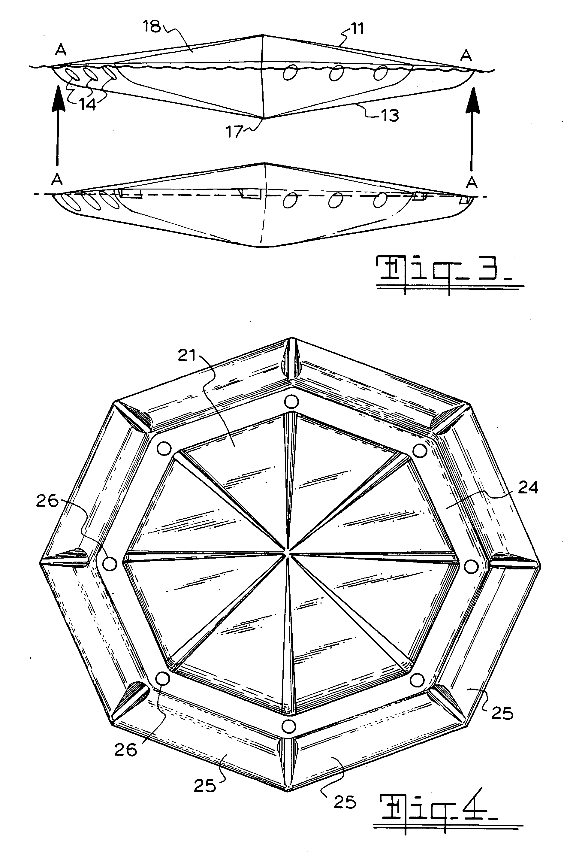
[0037]FIG. 3 is a side view and side schematic view of the embodiment in FIG. 1;

second embodiment

[0038]FIG. 4 is a top perspective view of this invention;

[0039]FIG. 5 is a top isometric view of a second embodiment of this invention;

[0040]FIG. 6 is a top perspective of an exploded view of the embodiment of FIG. 5;

[0041]FIG. 7 is a side view and side schematic view of the embodiment of FIG. 5;

third embodiment

[0042]FIG. 8 is a top plan view of this invention;

[0043]FIG. 9 is a side schematic view of the embodiment of FIG. 10;

[0044]FIG. 10 is a side view of the embodiment of FIG. 10.

[0045]FIG. 11 is a top perspective of an exploded view of the embodiment of FIG. 10;

[0046]FIG. 12 is a section view of the interior of the embodiment of FIG. 10;

[0047]FIG. 13 is a top isometric view of the embodiment in FIG. 10 with the flotation fingers covered;

[0048]FIG. 14 is a top exploded view of the embodiment in FIG. 10 with the baffle inserted;

[0049]FIG. 15 is an isometric view of four octagonal modules in closest pack arrangement of the embodiment in FIG. 10;

[0050]FIG. 16 is a top isometric view of a fourth hexagonal embodiment of this invention;

[0051]FIG. 17 is a right side view of the embodiment of FIG. 16;

[0052]FIG. 18 is a front side section view of the embodiment of FIG. 16 with enlarged floatation pods;

[0053]FIG. 19 is an exploded isometric view of the embodiment of FIG. 16;


PUM


Abstract

A floating modular cover for a water storage consisting of a plurality of modules in which each module includes a chamber defined by an upper surface and a lower surface there being openings in the upper surface to allow ingress of water into said chamber and openings in the upper surface to allow air to flow into and out of said chamber depending on the water level within said chamber to provide ballast for each module floats. The modules prevent water evaporation from the area covered and the shape and size is selected to ensure that the modules are stable in high wind conditions and don't form stacks. The modules may be made from identical hexagonal or octagonal halves by blow moulding or thermoforming.

Description

BACKGROUND TO THE INVENTION [0001] In regions of high evaporation and seasonal rainfall water loss from large open storages due to evaporation is high and is difficult to control. [0002] Evaporation control in relatively small areas of a few hectares or less is usually achieved with a cover over the total surface and anchored at the edges. Australian Patent Application No. 198429445 discloses a water evaporation suppression blanket comprising of interconnected buoyant segments cut from tyres cut orthogonal to the axis of the tyre and assembled in parallel or staggered array. [0003] Australian Patent Application No. 199964460 discloses a modular floating cover to prevent loss of water from large water storages through the natural process of evaporation. Comprising of modular units joined together by straps or ties, manufactured from impermeable polypropylene multi-filament, material welded together to form a sheet with sleeves. The sleeves are filled with polystyrene or polyurethane ...

Claims


Application Information

Patent Timeline
Patent Type & Authority Applications(United States)
IPC IPC(8): B65D88/34
CPCB65D88/36B65D90/42E04H4/103
Inventor CAP, GEORGE JAROSLAVWOODFIELD, ROSS
Owner AQUA GUARDIAN GROUP
Why Eureka
Try Eureka