Linear Electromechanical Vibrator with Axially Movable Magnet

Inactive Publication Date: 2008-01-03
VIRGINIA TECH INTPROP INC
View PDF9 Cites 62 Cited by
  • Summary
  • Abstract
  • Description
  • Claims
  • Application Information

AI Technical Summary

Benefits of technology

[0005]The present invention provides an electromagnetic vibrator having a movable magnet. The magnet moves in an axial direction (linearly or along a curved path). The movable magnet is magnetized in the axial direction. Two bumper magnets are disposed axially in-line with the movable magnet. The bumper magnets are oriented such that they magnetically repel the movable magnet. In operation, the movable magnet is not always required to “bump” up against the bumper magnets (although this may be beneficial in some applications); rather, movement of the movable magnet in a first direction under the influence of an externally applied electric field followed by a repelling force of a bumper magnet at the end of the pathway for travel results in a “vibration” that emanates from the housing in which the moveable magnet is located, This process is repeated at the other end of the pathway traveled by the moveable magnet. That is, the mass of the moveable magnet, and its oscillatory movement from one end to another along an axial pathway results in vibrations being

Problems solved by technology

Such rotary vibrators are relatively expensive and complicated to manufacture because the motor requires assembly of many small parts.
Also, rotary vibrators tend to be energy inefficient.
That is, the mass of the moveable magnet, and its oscillatory movement fr

Method used


Image

  • Linear Electromechanical Vibrator with Axially Movable Magnet
  • Linear Electromechanical Vibrator with Axially Movable Magnet
  • Linear Electromechanical Vibrator with Axially Movable Magnet

Examples


Embodiment Construction

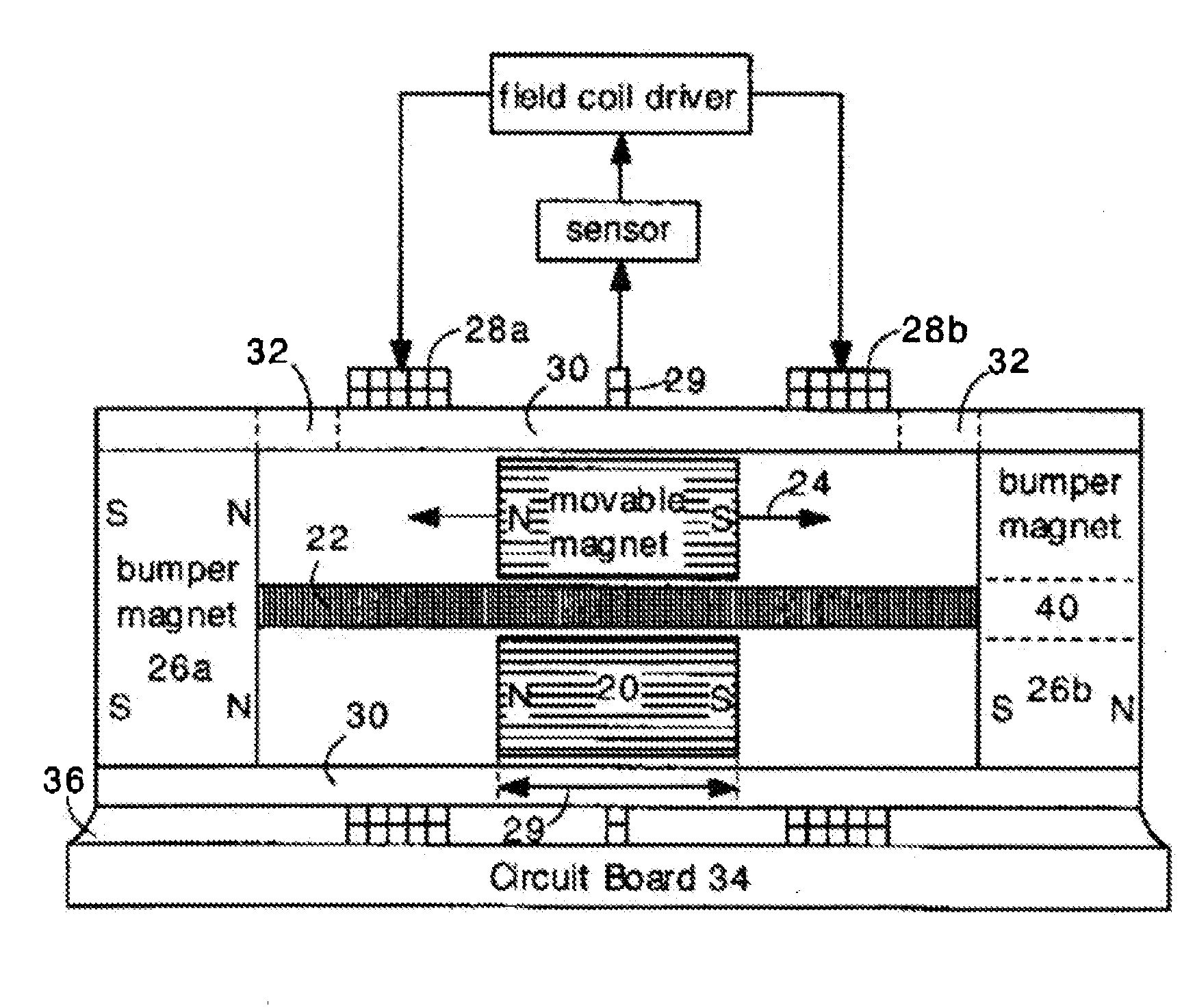
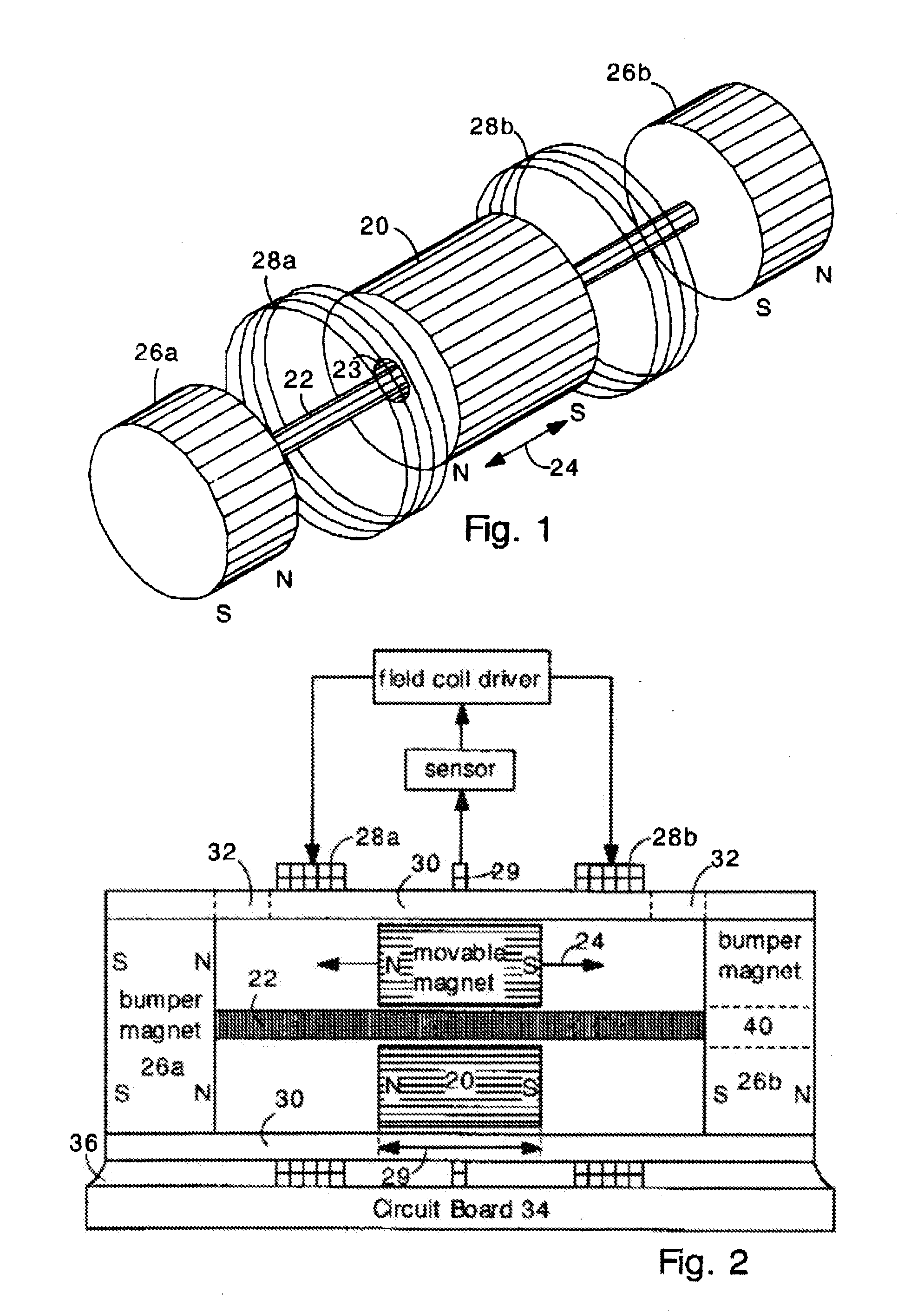
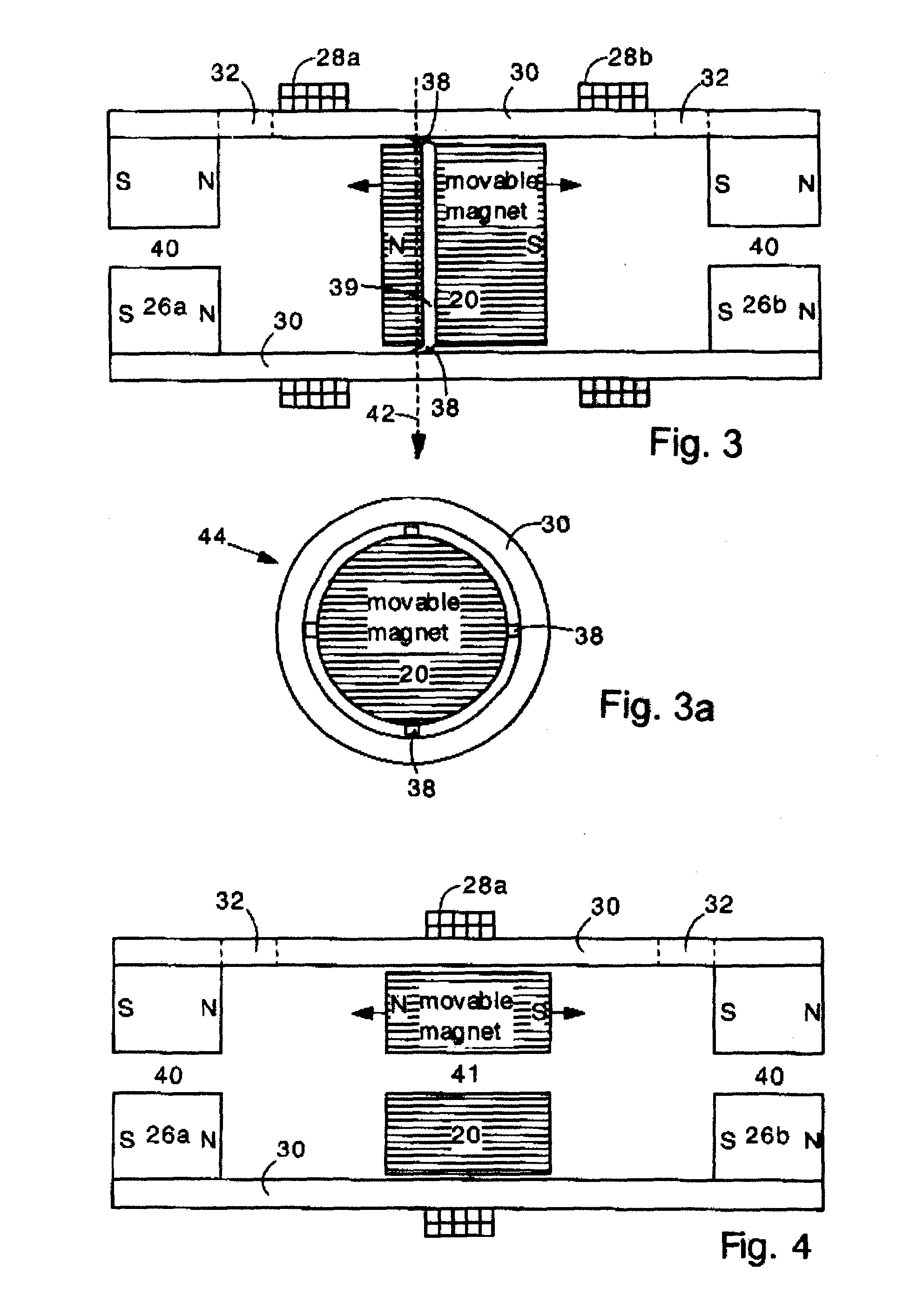
[0025]The present invention provides an electromagnetic vibrator particularly well suited for use in portable electronic devices such as cell phones, toys, games, personal massage devices and the like. The electromagnetic vibrator has a movable magnet that can move in an axial direction. One or more electromagnetic field coils surround the movable magnet. Bumper magnets are disposed on opposite ends of the vibrator, and constrain the axial motion of the movable magnet. When an alternating current is provided in the field coil, the movable magnet oscillates linearly in the axial direction. The movable magnet rebounds from the bumper magnets, thereby creating vibration. This rebounding can be with or without actual touching of the bumper magnets which are poled to repel the oncoming moveable magnet. The movable magnet may have a toroidal shape (other shapes being possible in different applications) and may be disposed on a straight rod to linearly constrain the motion of the movable m...


PUM


Abstract

An electromagnetic vibrator has a movable magnet that can move linearly in an axial direction. A field coil surrounds the movable magnet. Magnetic bumpers are disposed on opposite ends of the vibrator, and are oriented to repel the movable magnet. When an alternating current is provided in the field coil, the movable magnet oscillates linearly in the axial direction, bumping against the magnetic field of the bumper magnets and thereby creating vibration. The movable magnet may have a toroidal shape and be disposed on an axial shaft to linearly constrain the motion of the movable magnet. Two field coils can be provided to simultaneously create push and pull forces on the movable magnet. The bumper magnets can be replaced with compression springs. The electromagnetic vibrator can be very small and energy efficient; it is well suited for use in portable electronic devices, cell phones, toys, industrial mixers, and massage devices.

Description

FIELD OF THE INVENTION[0001]The present invention relates generally to linear electromagnetic vibrators, and, more particularly, to a non-rotary electromagnetic vibrator having a movable magnet that oscillates axially under the influence of an axial field coil.BACKGROUND OF THE INVENTION[0002]Electromagnetic shakers and vibrators are commonly used in cellular telephones and other portable electronic devices. Such vibrators are activated in order to silently alert a user of an incoming message.[0003]Conventional cell phone vibrators typically have a miniature rotary motor with an eccentric mass attached to the rotor. The eccentric mass produces oscillating acceleration forces when the motor is activated. Such rotary vibrators are relatively expensive and complicated to manufacture because the motor requires assembly of many small parts. Also, rotary vibrators tend to be energy inefficient. In portable electronic devices such as cell phones, energy efficiency is critical.[0004]Accordi...

Claims


Application Information

Patent Timeline
IPC IPC(8): H02K33/00H02K35/00
CPCH02K33/16
Inventor FULLER, CHRISBOOTH, STEVEOSBORNE, GEORGE
Owner VIRGINIA TECH INTPROP INC
Why Eureka
Try Eureka