Superconducting rotating machines with stationary field coils

a superconducting coil and rotating machine technology, applied in the direction of windings, magnetic circuit rotating parts, magnetic circuit shape/form/construction, etc., can solve the problems of increasing the complexity of the overall system design, adding the superconducting field coil to substantial thermal stresses, centrifugal stresses, etc., and causing electrical design challenges. to be difficult to design, fabricate and operate such a rotor

Active Publication Date: 2008-01-03
GENERAL ELECTRIC CO
View PDF26 Cites 30 Cited by
  • Summary
  • Abstract
  • Description
  • Claims
  • Application Information

AI Technical Summary

Problems solved by technology

This transfer of cryogenic fluid from a stationary cryocooler to a rotating cooling loop adds considerable complexity to the overall system design.
In addition, installation of a superconducting field coil on the rotor subjects the superconducting field coil to substantial thermal stresses, centrifugal stresses, and electrical design challenges.
One such electrical design challenge is providing an electrical connection through the rotor to power the superconducting field coil.
Ac

Method used


Image

  • Superconducting rotating machines with stationary field coils
  • Superconducting rotating machines with stationary field coils
  • Superconducting rotating machines with stationary field coils

Examples


Embodiment Construction

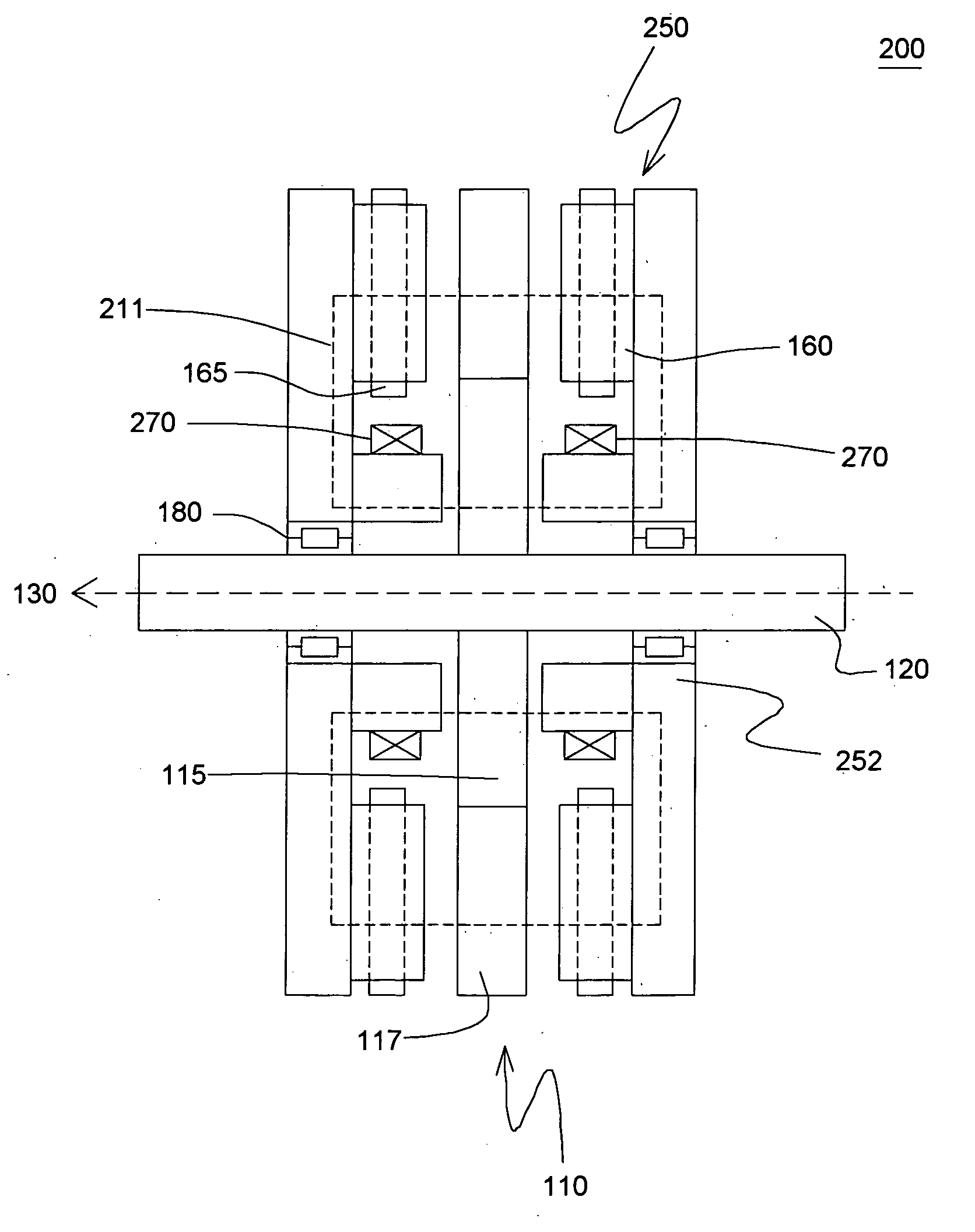
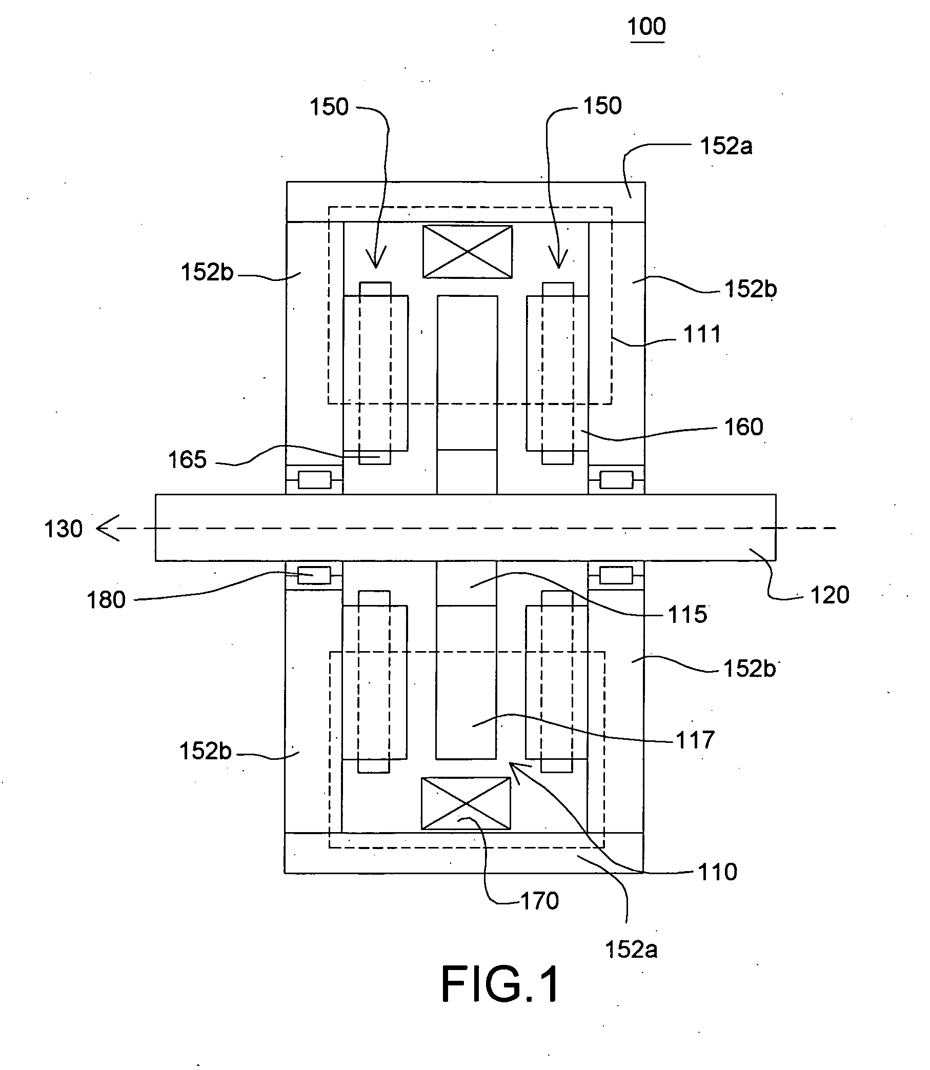
[0018]FIG. 1 is a cross-sectional view of an exemplary embodiment of an electrical machine 100. The machine 100 may operate as a motor and / or as a generator as desired. The machine 100 includes a stator assembly 150 having a stator yoke 152, a pair of armature coils 165 mechanically coupled to the stator yoke 152, and a stationary superconducting field coil 170. The stator yoke 152 comprises a magnetic material, and a variety of materials can be used to form the yoke 152, non-limiting examples of which include iron, magnetic steel, silicon iron, and iron-cobalt alloys. In one example, the cross bar portion 152a of the yoke is formed of a different material than are the legs 152b of the yoke. For example, in a particular embodiment cross-bar 152a comprises a solid material and legs 152b comprise laminates, in order to reduce AC field induced eddy current losses in the yoke. The machine 100 further includes a shaft 120 rotatably mounted in the stator yoke 152 and formed of a non-magne...


PUM


Abstract

A machine includes a stator assembly that includes a stator yoke, a pair of armature coils mechanically coupled to the stator yoke, and a stationary superconducting field coil. The stator yoke comprises a magnetic material. The machine further includes a shaft rotatably mounted in the stator yoke, the shaft comprising a non-magnetic material. The machine further includes a rotor assembly rotationally engaged with the shaft. The rotor assembly includes a rotor disk extending between the armature coils, the rotor disk having an inner portion and an outer portion. The outer portion of the rotor disk includes a number of circumferentially-spaced, magnetic poles. The rotor disk is coupled to the shaft for rotation about the shaft and generation of a rotating permeance wave. The stationary superconducting field coil is disposed between the stator yoke and the rotor disk, and the stationary superconducting field coil is configured as a stationary magneto-motive force (MMF) source for the rotating permeance wave produced by the rotor assembly to produce a rotating magnetic field.

Description

STATEMENT REGARDING FEDERALLY SPONSORED RESEARCH & DEVELOPMENT[0001]This invention was made with Government support under contract number FA8650-04-G-2466-001 awarded by the United States Air Force (USAF). The Government has certain rights in the invention.BACKGROUND OF THE INVENTION[0002]The present invention relates generally to electrical motor / generators, and more particularly to machines including superconducting windings.[0003]Typically, designs for superconducting electric machines include a superconducting field coil installed on the rotor. The superconducting coil is maintained at a temperature below its critical temperature using a continuous supply of cryogenic fluid, such as liquid helium (He) for conventional superconductors and liquid nitrogen (N2) or neon (Ne) for high temperature superconductors (HTS). In order to cool the field coil, the cryogenic fluid is typically supplied to the superconducting field coil from a stationary cryocooler through a transfer coupling t...

Claims


Application Information

Patent Timeline
IPC IPC(8): H02K17/00H02K19/20H02K3/00
CPCH02K19/103Y02E40/622H02K55/02H02K19/24Y02E40/60
Inventor QU, RONGHAIBRAY, JAMES WILLIAM
Owner GENERAL ELECTRIC CO
Why Eureka
Try Eureka