
Control System for Static VAR Compensator

a control system and static var technology, applied in the direction of electric variable regulation, process and machine control, instruments, etc., can solve the problems of tertiary harmonic voltage distortion, adverse effects on the other devices connected to the system, and obstructing the sound operation of the svc, etc., to achieve the effect of restricting the outflow

Inactive Publication Date: 2008-01-03
MITSUBISHI ELECTRIC CORP
View PDF4 Cites 28 Cited by
  • Summary
  • Abstract
  • Description
  • Claims
  • Application Information

AI Technical Summary

Benefits of technology

[0011]According to an aspect of the invention, in a control system for a static var compensator that performs phase control of a current of a reactor for each phase by a thyristor and thus controls reactive power, the thyristor of each phase is controlled so that the quantity of generated tertiary harmonic current of each phase in the static var compensator becomes equal. According to the invention, the outflow of the tertiary harmonic current toward the system can be restrained by an inexpensive system.

Problems solved by technology

However, when the system voltage includes a three-phase unbalanced component, the tertiary harmonic current is not canceled and flows out toward the system.
This causes problems of obstruction to sound operations of the SVC and adverse effects on the other devices connected to the system.
However, JP-A-61-221533, and R. Mohan Mathur and Rajiv K. Varma disclose that simply equalizing the magnitude of the fundamental wave currents is not effective and may conversely expand the tertiary harmonic current.
In the traditional SVC, since the tertiary harmonic current flows out toward the system when the system voltage is unbalanced, there is a problem that the tertiary harmonic voltages is distorted and adversely affects the other devices connected to the system.
Also, since the tertiary harmonic filter must be provided, there is a problem of increase in cost.
There is still another problem that if the currents of the three phases are controlled to be equal in order to restrain the tertiary harmonic current, the control becomes unstable and conversely expands the tertiary harmonic.

Method used


Image

  • Control System for Static VAR Compensator
  • Control System for Static VAR Compensator
  • Control System for Static VAR Compensator

Examples


embodiment 1

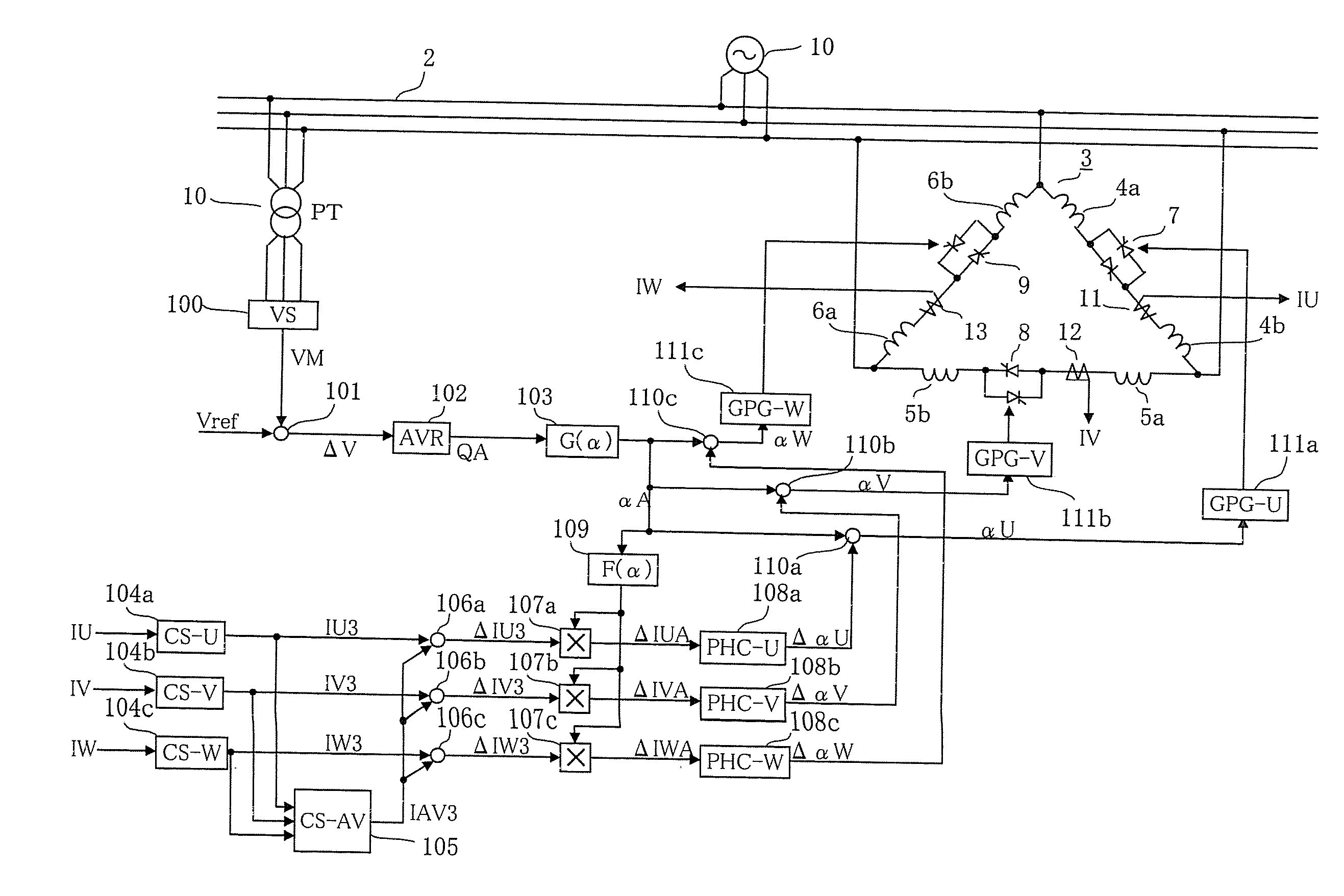
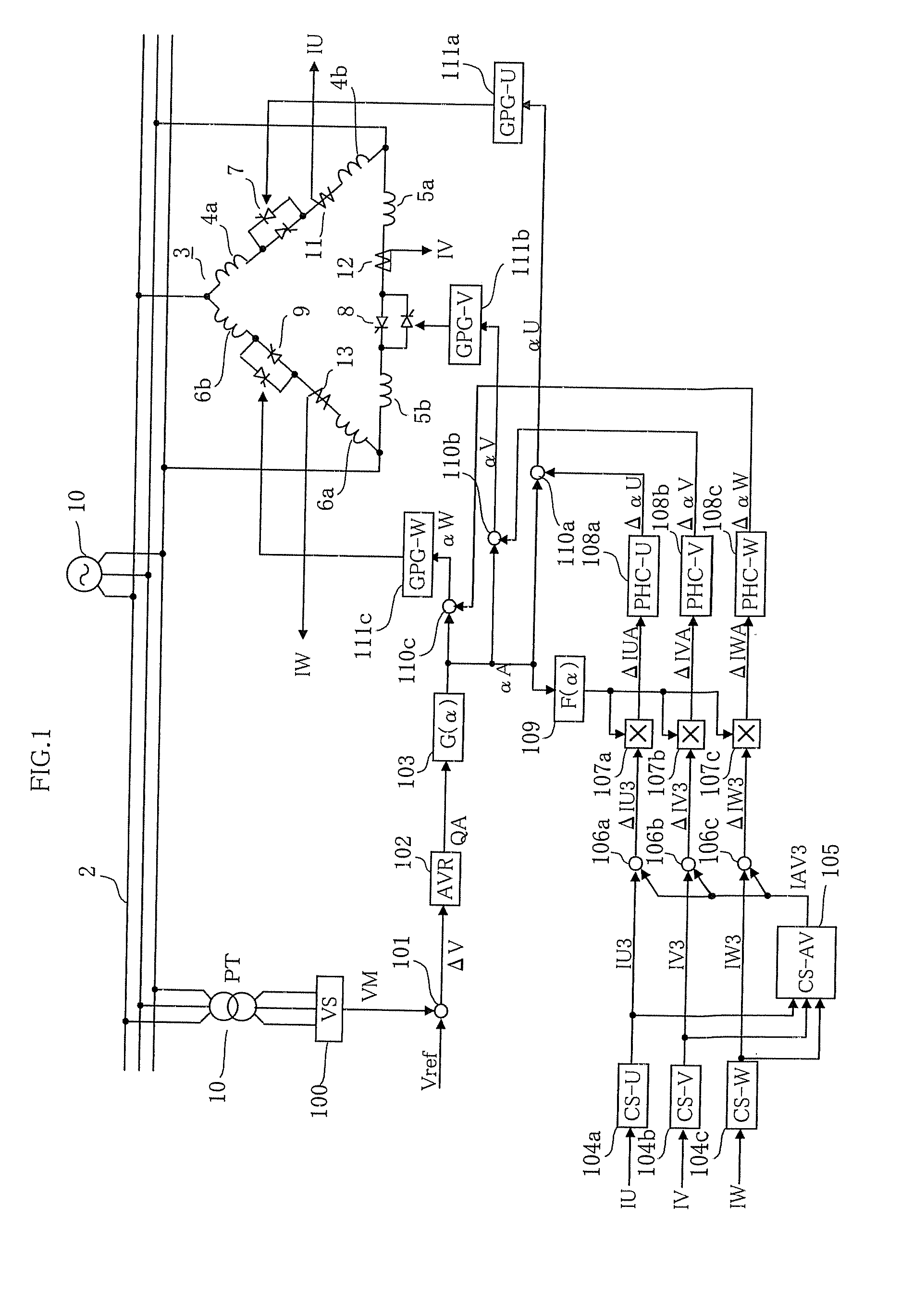
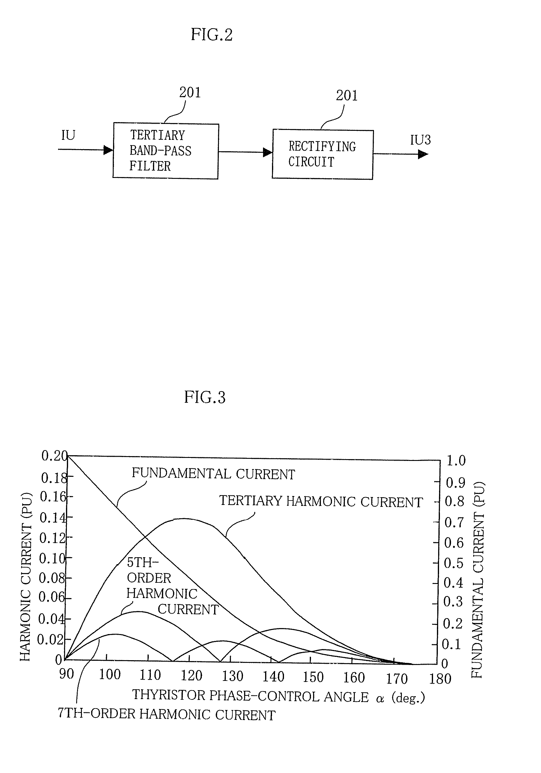
[0018]Hereinafter, Embodiment 1 of the invention will be described with reference to FIGS. 1 to 5. FIG. 1 is a block diagram showing an exemplary configuration of a power system in which an exemplary SVC is installed and an exemplary tertiary harmonic restraining and control circuit. FIG. 2 is a circuit diagram showing an exemplary detection unit for detecting the quantity of a tertiary harmonic current flowing through the SVC. FIG. 3 is a graph showing an exemplary relation between the quantity of generated tertiary harmonic current in the SVC and the thyristor phase-control angle. FIG. 4 is a graph showing an exemplary sensitivity coefficient that represents a change in the quantity of the tertiary harmonic current in the SVC with respect to a change in a thyristor phase-control angle α. FIG. 5 is a graph showing an exemplary linearization function for linearizing the nonlinear relation of the sensitivity coefficient shown in FIG. 4. In the drawings, the same numerals represent th...


PUM


Abstract

In a control system for a static var compensator that performs phase control of a current of a reactor for each phase by a thyristor and thus controls reactive power, a detecting unit that detects a tertiary harmonic current flowing through each phase of the static var compensator is provided, and on the basis of the tertiary harmonic current flowing through each phase detected by the detecting unit, the thyristor of each phase is controlled so that the quantity of generated tertiary harmonic current of each phase becomes equal, and therefore an outflow of the tertiary harmonic current toward a system can be restrained by an inexpensive method.

Description

BACKGROUND OF THE INVENTION[0001]1. Field of the Invention[0002]This invention relates to a control system for a static var compensator adapted for performing phase control of a current of a reactor for each phase by a thyristor and thus controlling reactive power.[0003]2. Description of the Related Art[0004]It has been known that, in a static var compensator (hereinafter referred to simply as “SVC”) that performs phase control of a reactor current for each phase by a thyristor and thus controls reactive power, a harmonic current is generated when the magnitude of a reactor current is phase-controlled by a thyristor converter. For example, R. Mohan Mathur and Rajiv K. Varma, “Thyristor-based FACTS controller for electrical transmission systems”, published by Wiley-Interscience, 2002, p. 47-55, FIG. 3.9 shows the generation of a harmonic current. Since a tertiary harmonic current generated from TCR (thyristor controlled reactor) is large, outflow of the tertiary harmonic current towa...

Claims


Application Information

Patent Timeline
IPC IPC(8): G05F1/70
CPCG05F1/70Y02E40/12H02J3/1864Y02E40/10
Inventor TAKEDA, MASATOSHITEMMA, KOJI
Owner MITSUBISHI ELECTRIC CORP
Learn More