High Precision Voltage Source for Electrical Impedance Tomography

a voltage source and impedance tomography technology, applied in the field of high-precision voltage source for electrical impedance tomography, can solve the problems of limited bandwidth, large number of high-precision components, and manifested unfavorable patient safety, and achieve the effect of high precision and high accuracy

Active Publication Date: 2008-01-03
RENESSELAER POLYTECHNIC INST
View PDF8 Cites 39 Cited by
  • Summary
  • Abstract
  • Description
  • Claims
  • Application Information

AI Technical Summary

Benefits of technology

[0010] It is a further object of the present invention to directly measure the actual applied voltage and resulting current in an EIT system with high precis

Problems solved by technology

The ill-posedness of this inverse problem manifests itself through the small changes in surface current or voltage that sometimes result from large changes in the interior impedance distribution.
While such current sources have been developed for this application, they tend to have limited bandwidth, appl

Method used


Image

  • High Precision Voltage Source for Electrical Impedance Tomography
  • High Precision Voltage Source for Electrical Impedance Tomography
  • High Precision Voltage Source for Electrical Impedance Tomography

Examples


Embodiment Construction

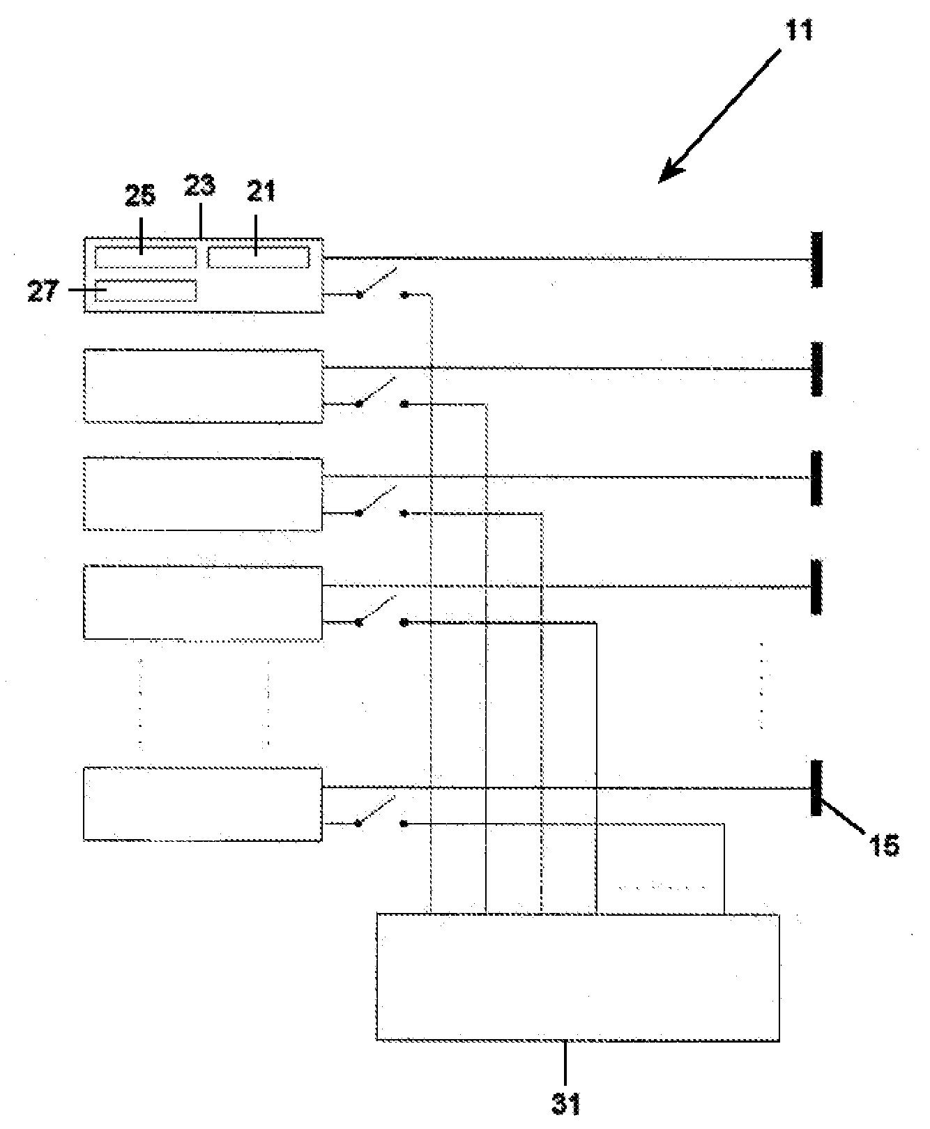
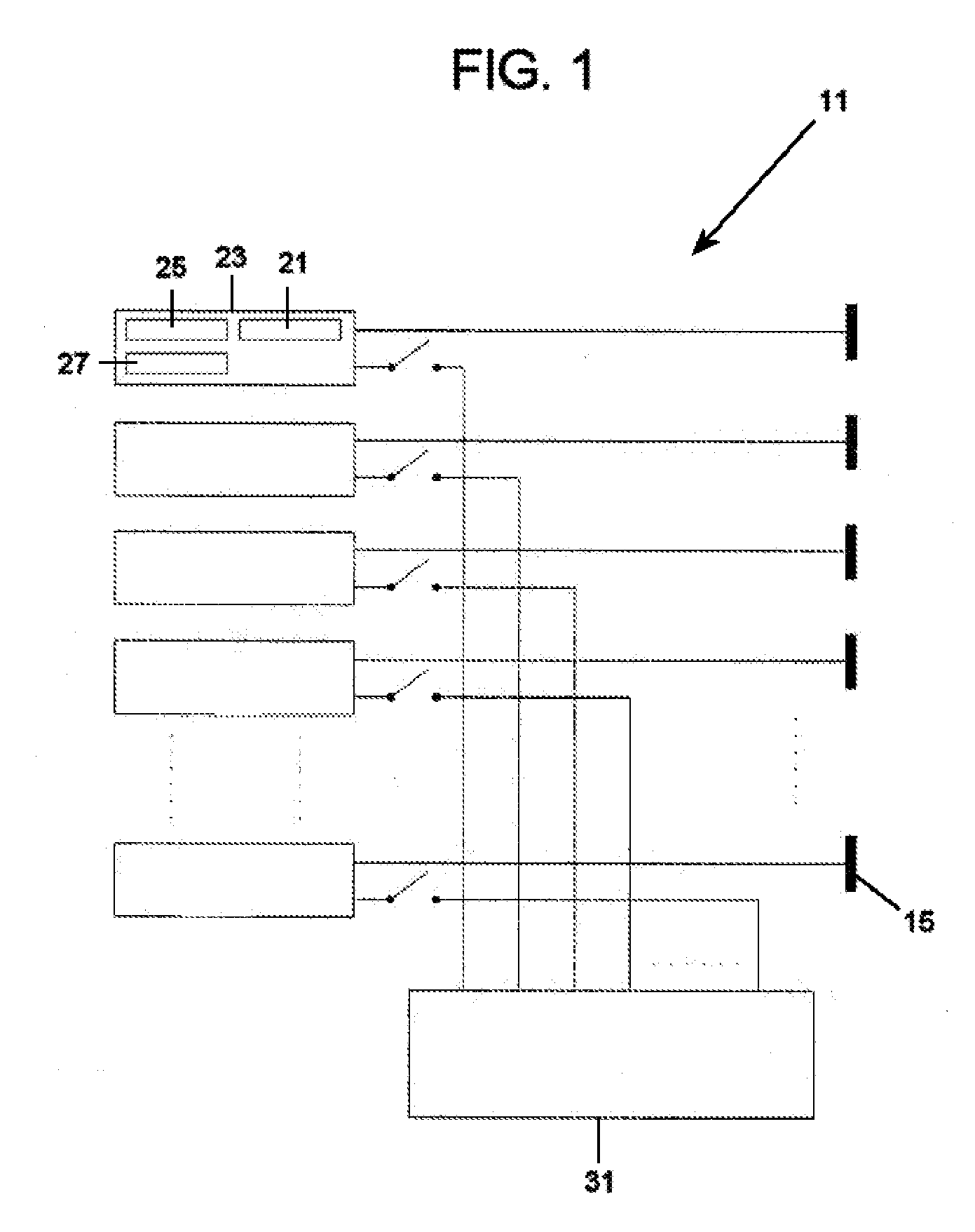
[0033] Referring now to the drawings, in which like reference numerals are used to refer to the same or similar elements, FIG. 1 is a block diagram of an applied-voltage EIT system 11 with L number of electrodes 15. Each electrode 15 is connected to a circuit 21 that includes a voltage source 23 for generating the applied voltage as well as an ammeter 25 to measure the applied current and a voltmeter 27 to directly measure the applied voltage. A switching network enables a single calibration circuit to be connected to any of the voltage source / ammeter / voltmeter circuits 21 to allow the whole system 11 to be calibrated to a single reference.

[0034] Though not shown in FIG. 1, the voltage sources 23 (with ammeters 25 and voltmeters 27), switches, and calibration circuit 31 each interface to a digital controller which sets the system configuration and collects digital measurements of voltage and current. A series of calibration steps, to be described below, are performed to collect cal...


PUM


Abstract

An EIT system includes a plurality of voltage sources for supplying a corresponding plurality of voltages to a corresponding number of other structures, voltage source calibration means for calibrating each voltage source, and switching means for individually connecting the calibration means to each voltage source in succession during a period when each other structure is in an inactive condition. Calibrating respective voltages and currents for each voltage source compensates for shunt impedance of each voltage source. A method for calibrating the system includes individually connecting the calibration means to each voltage source in succession during a period when each other structure is in an inactive condition for calibrating all of said voltage sources in the same way.

Description

CROSS-REFERENCE TO RELATED APPLICATION [0001] This U.S. patent application claims priority on, and all benefits available from U.S. provisional patent application 60 / 641,508 filed Jan. 5, 2005, all of which is incorporated here by reference.STATEMENT OF GOVERNMENT INTEREST [0002] Development of the present invention was supported, in part, by CenSSIS, the Center for Subsurface Sensing and Imaging Systems, under the Engineering Research Center Program of the National Science Foundation (Award number EEC-9986821).FIELD AND BACKGROUND OF THE INVENTION [0003] The present invention relates generally to the field of EIT, and in particular to a new and useful electrical impedance imaging apparatus and a method for calibrating the electrical impedance imaging apparatus. [0004] Electrical impedance tomography is an imaging modality which displays the spatial distribution of the complex conductivity distribution inside a body. An excitation is applied to electrodes on the body surface, result...

Claims


Application Information

Patent Timeline
IPC IPC(8): G01R35/00
CPCA61B5/0536
Inventor SAULNIER, GARY J.LIU, NINGROSS, ALEXANDER S.
Owner RENESSELAER POLYTECHNIC INST
Why Eureka
Try Eureka