Methods for improving wireless communications when interference or signal loss is directional in nature

a wireless communication and signal loss technology, applied in wireless communication, wireless commuication services, digital transmission, etc., can solve the problems of cost in both hardware/software implementation and beam search or beam forming processing time, and achieve the effect of increasing link gains

Active Publication Date: 2008-01-03
INTERDIGITAL TECH CORP
View PDF13 Cites 40 Cited by
  • Summary
  • Abstract
  • Description
  • Claims
  • Application Information

AI Technical Summary

Benefits of technology

[0021] When the exchanged signals are transmitted by the client station, and when soft packet combining is performed at an intended receiver, the virtual beam former advantageously allows a switched beam smart antennas to approximate a true beam forming device. As a result, increased link gai...

Problems solved by technology

Fine-combed scanning of every direction, using steerable or beam formed smart antennas, is possible but can be very costly in terms of both hardware/software implementation and beam searching or beam forming processing time.
Example scenarios where this condition may exist include interference that is dominant in one d...

Method used


Image

  • Methods for improving wireless communications when interference or signal loss is directional in nature
  • Methods for improving wireless communications when interference or signal loss is directional in nature
  • Methods for improving wireless communications when interference or signal loss is directional in nature

Examples


Embodiment Construction

[0035] The present invention will now be described more fully hereinafter with reference to the accompanying drawings, in which preferred embodiments of the invention are shown. This invention may, however, be embodied in many different forms and should not be construed as limited to the embodiments set forth herein. Rather, these embodiments are provided so that this disclosure will be thorough and complete, and will fully convey the scope of the invention to those skilled in the art. Like numbers refer to like elements throughout.

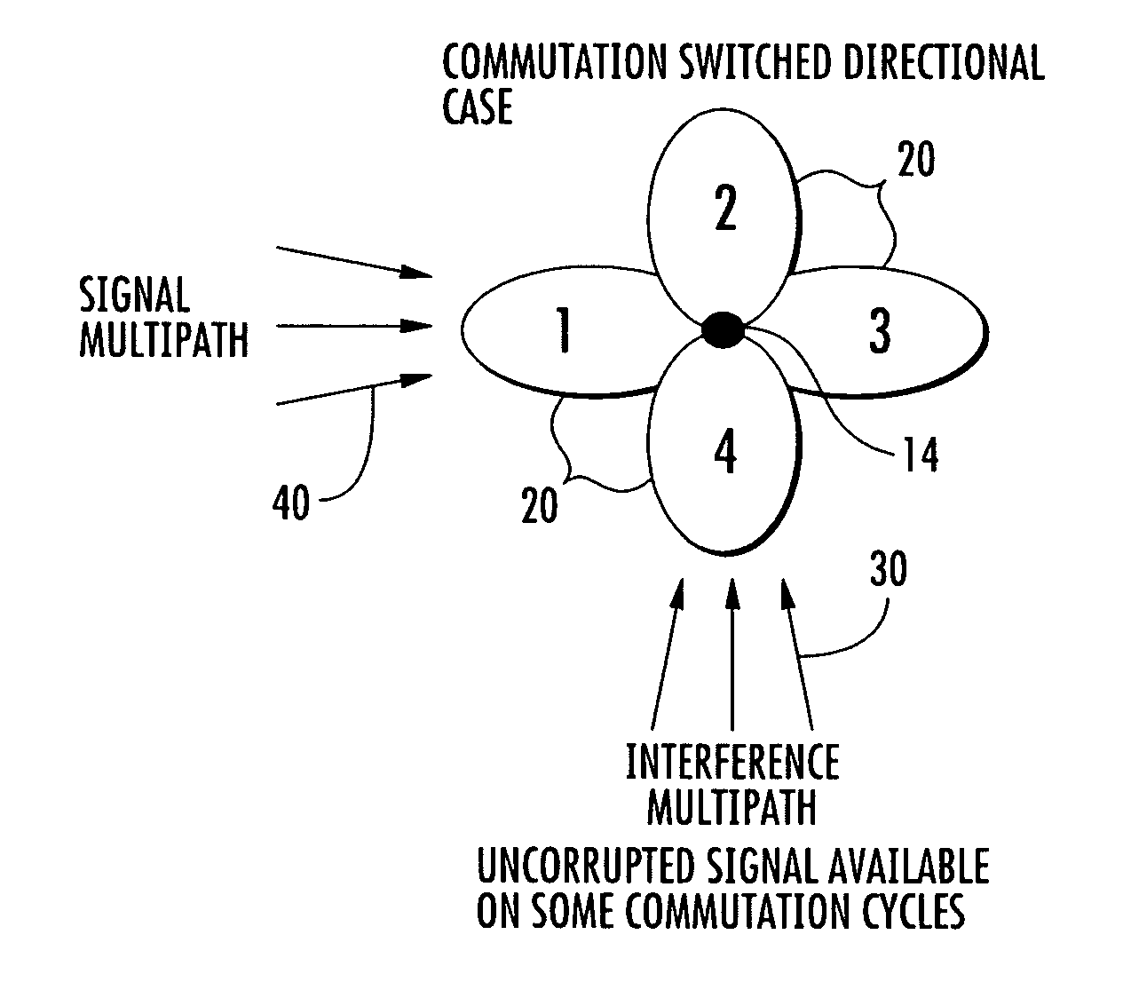
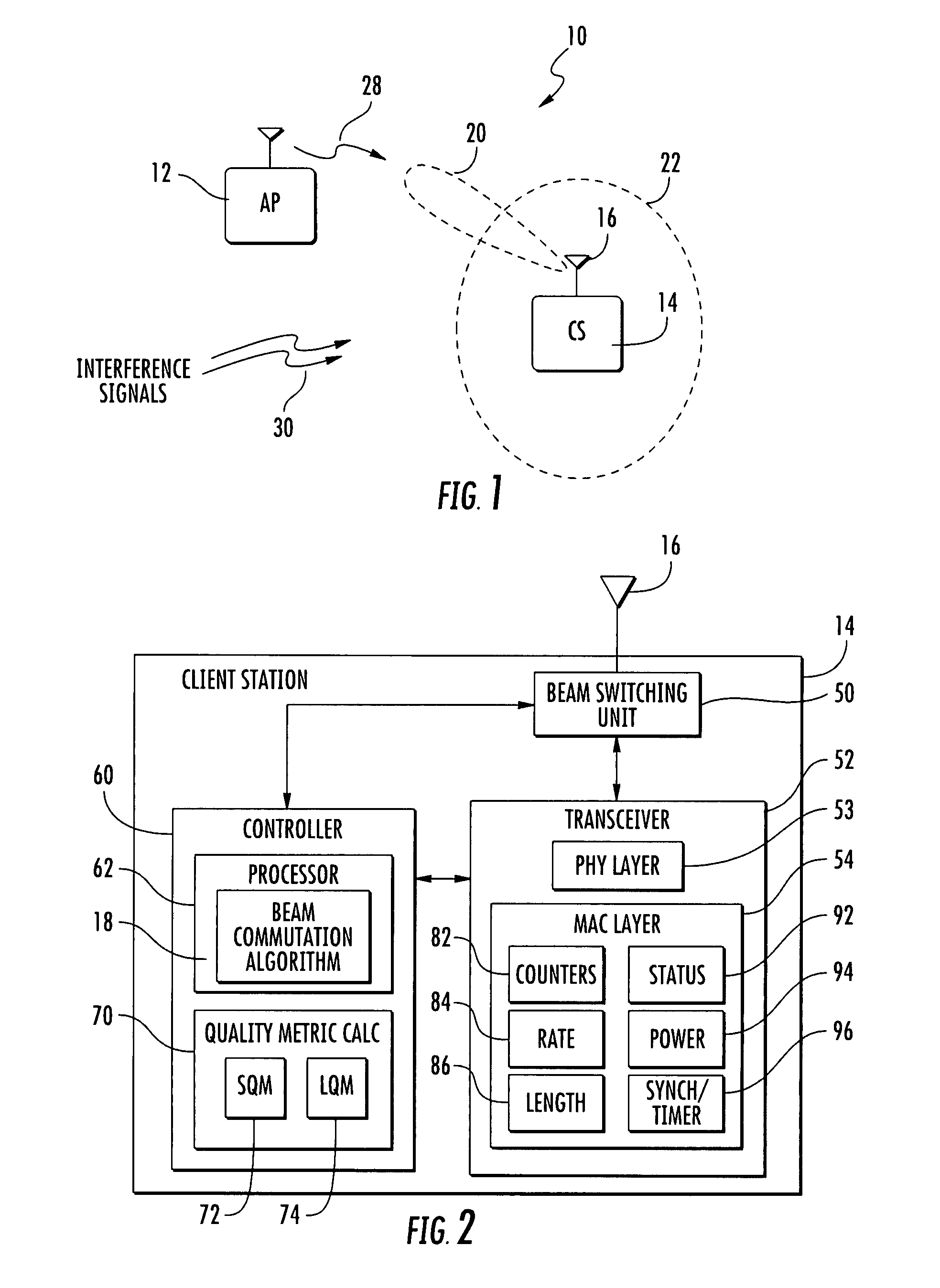
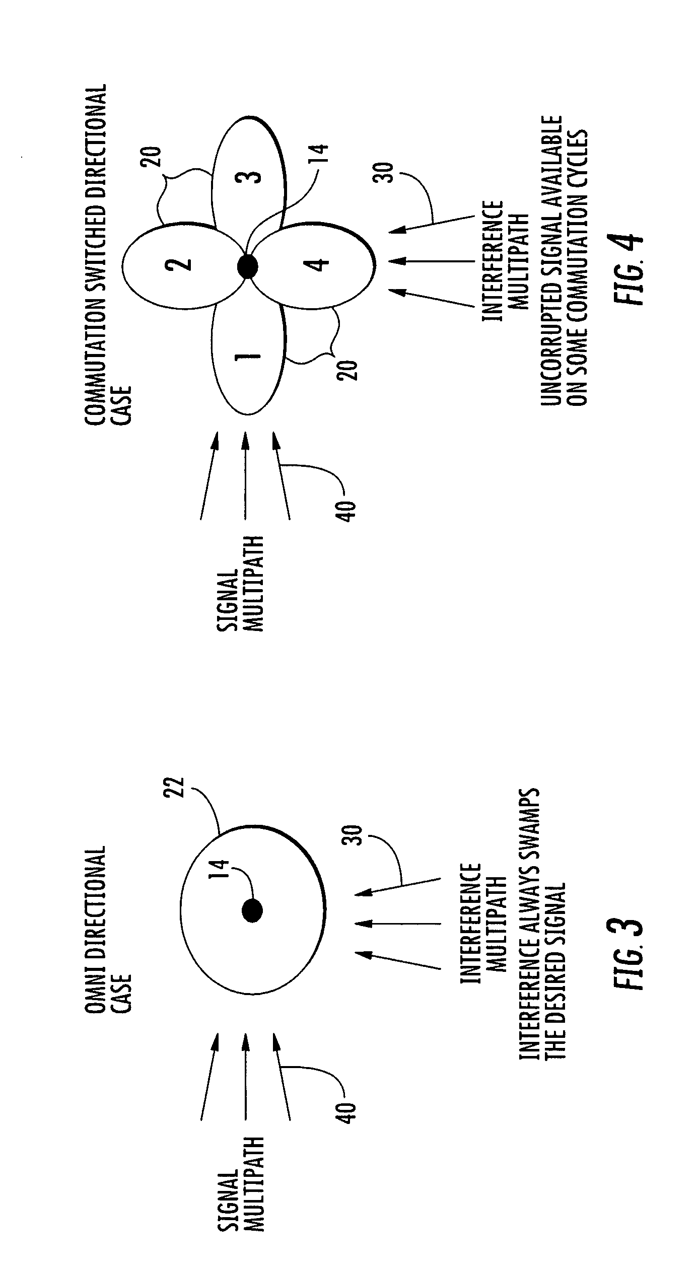
[0036] Referring initially to FIGS. 1 and 2, an 802.11 wireless local area network (WLAN) 10 includes an access point 12, and a client station 14 operating with a subscriber based smart antenna 16 in accordance with the present invention. The smart antenna 16, which will also be referred to as a switched beam antenna, generates a plurality of antenna beams in response to a beam commutation algorithm 18. The antenna beams generated by the smart antenna 16...


PUM


Abstract

A client station in a wireless local area network (WLAN) communication system includes a beam commutation algorithm and a smart antenna responsive to the beam commutation algorithm for selecting one of a plurality of directional antenna beams. The smart antenna is configured as a virtual omni-directional antenna by using a commutation of switched directional antenna beams. A switched directional antenna system that performs a commutation sequencing can be blind to environmental conditions and changes.

Description

RELATED APPLICATION [0001] This application claims the benefit of U.S. Provisional Application Ser. No. 60 / 803,803 filed Jun. 2, 2006, the entire contents of which are incorporated herein by reference.FIELD OF THE INVENTION [0002] The present invention relates to the field of wireless local area networks (WLANs), and more particularly, to a client station operating with a smart antenna in a WLAN. BACKGROUND OF THE INVENTION [0003] Smart antenna technology is directed to antennas having the ability to change radio beam transmission and reception patterns to suit the environment within which radio communication systems operate. Smart antennas have the advantage of providing relatively high radio link gain without adding excessive cost or system complexity. [0004] Smart antenna technology has been used in wireless communication systems for decades, and has recently been investigated for use in wireless local area networks (WLANs). In a WLAN, a client station (CS) is a device used by a ...

Claims


Application Information

Patent Timeline
IPC IPC(8): H04Q7/00H04W28/04H04W84/12H04W88/02
CPCH01Q3/2611H04L1/1887H04W88/02H04W84/12H04W28/04
Inventor CHA, INHYOKBALDWIN, KEITHLI, YINGXUE
Owner INTERDIGITAL TECH CORP
Why Eureka
Try Eureka