Microfluidic devices

a microfluidic device and microfluidic technology, applied in fluorescence/phosphorescence, laboratory glassware, instruments, etc., can solve the problems of high cost, high cost, and the limit of the smallest volume of reagent that can effectively be used, and achieve the effect of quick, effective and inexpensive us

Inactive Publication Date: 2008-01-03
BIO RAD LAB INC
View PDF98 Cites 895 Cited by
  • Summary
  • Abstract
  • Description
  • Claims
  • Application Information

AI Technical Summary

Benefits of technology

[0009] The present invention provides substrates having individual fluid handling modules that can be combined into fluid processing systems so as to perform multi-step processing of isolated components, which is essential to perform biological, chemical and diagn

Problems solved by technology

However, virtually all microfluidic devices are based on flows of streams of fluids; this sets a limit on the smallest volume of reagent that can effectively be used because of the contaminating effects of diffusion and surface adsorption.
As the dimensions of small volumes shrink, diffusion becomes the dominant mechanism for mixing leading to dispersion of reactants; moreover, surface adsorption of reactants, while small, can be highly detrimental when the concentrations are low and volumes are small.
As a result current microfluidic technologies cannot be reliably used for applications involving minute quantities of reagent; for example, bioassays on single cells or library searches involving single beads are not easily performed.
However, essentially all enabling technology for microfluidic systems developed thus far has focused on single phase fluid flow and there are few equivalent active means to manipulate droplets requiring the development of drop

Method used


Image

  • Microfluidic devices
  • Microfluidic devices
  • Microfluidic devices

Examples


example 1

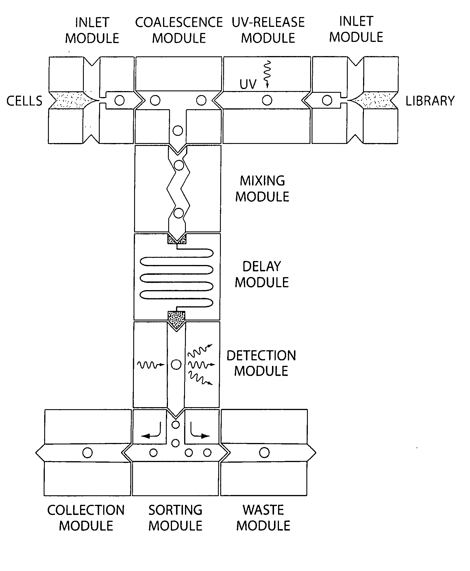
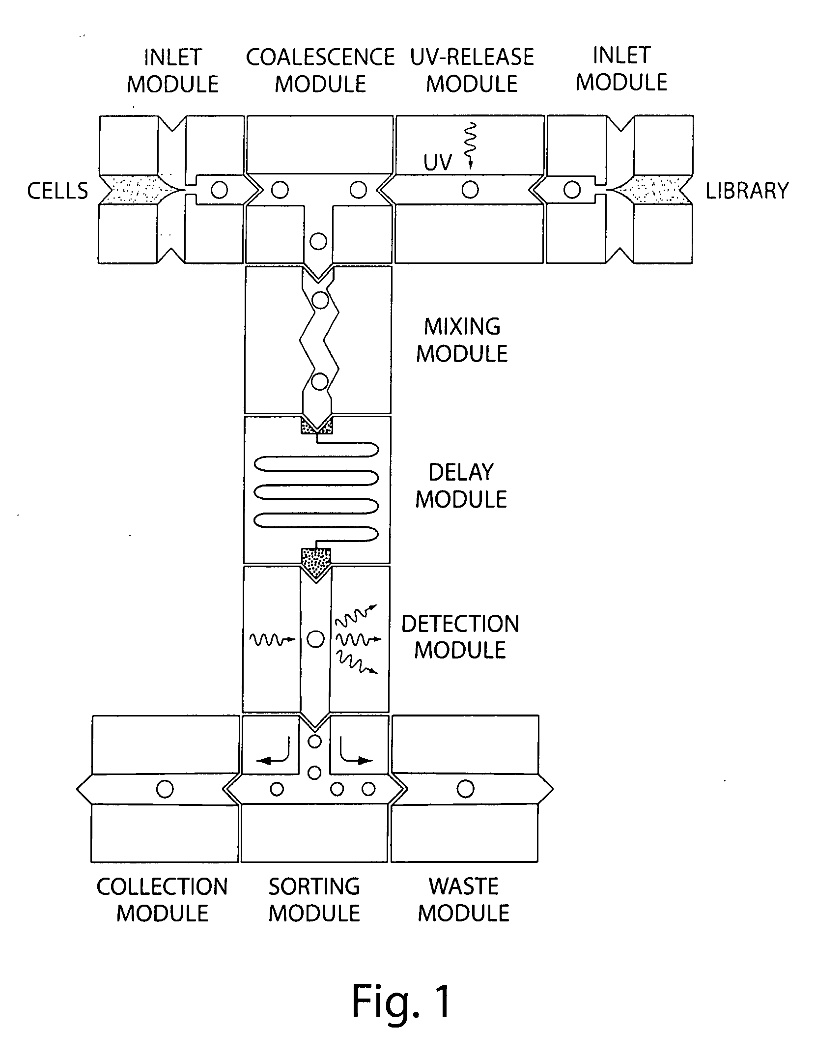
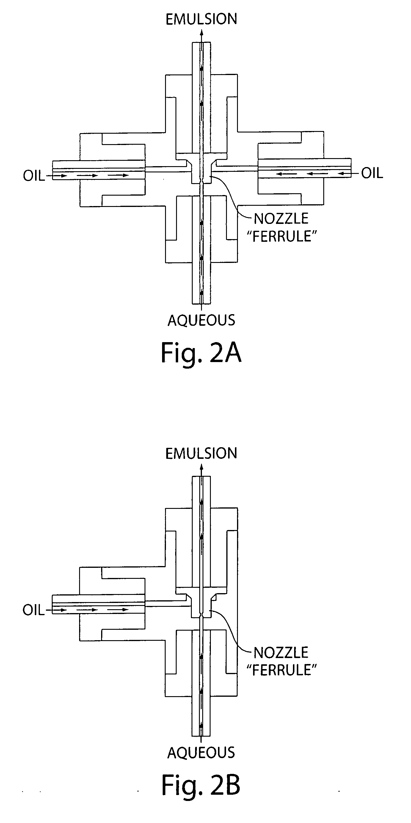
[0322] The present invention provides methods for preparing a library of droplet emulsions, where each of the droplets is of the same, predetermined size (monodisperse). Further, present invention provides methods for deterministic lateral displacement for continuous particle separation, which can occur within droplets on a microfluidic device.

[0323] Particles in solution are usually separated according to size by exclusion or hydrodynamic chromatography. In the former, a sample mixture is injected at one end of a tube packed with porous beads and then washed through the tube. Particles smaller than the pore sizes enter the beads, which lengthen their migration path, and so they are on average eluted later than larger particles. Zones of particles of a given size broaden, however, because particles in each zone take many different paths, leading to different retention times. This multipath effect reduces the resolution of size-exclusion chromatography. In hydrodynamic chromatograph...

example 2

[0334] The present invention provides methods for performing polymerase chain reaction (PCR). PCR can be performed on a drop-by-drop basis in a microfluidic device according to the present invention. A monolithic chip can be provided wherein the heating and cooling lines are built into the chip and a sorting means is provided. Advantages of performing PCR in droplets on such a chip are that the chip is disposable and the reaction can be repeated without cleaning the device between reactions. Furthermore, the chip provides a convenient way of getting all the components to perform PCR in the droplets in the right concentration. Additionally, the PCR is more efficient because the heat transfer is more efficient due to the small volume. This provides for shorter incubation / residence times. Droplets containing the nucleic acids, all PCR primers, and, if present, beads are generated one at a time at rates between 100 and 20,000 droplets per second. The droplets can then be sent through a ...

example 3

[0357] The present invention provides methods for performing isothermal-type amplification methods on a microfluidic device. Isothermal amplification is an alternative to the standard PCR techniques described herein. Isothermal amplification is used to reduce the relative amount of background DNA in a sample. Primers are generally used in a constant temperature means of amplification. Isothermal amplification is applicable for SNP detection. Once the DNA is amplified by isothermal amplification there are several well-known means for detecting which nucleotide polymorphism is present. These include, but are not limited to; allele specific primer extension, oligonucleotide ligation assay, mini-sequencing, fluorescence polarization, etc. Isothermal amplification is also applicable for DNA sequencing preparation. The isothermally-amplified DNA can be attached to a solid phase within a droplet or placed within a parking space on chip. The beads or parking spaces can be accessed and the a...


PUM

PropertyMeasurementUnit
Timeaaaaaaaaaa
Massaaaaaaaaaa
Massaaaaaaaaaa

Abstract

The present invention provides novel microfluidic substrates and methods that are useful for performing biological, chemical and diagnostic assays. The substrates can include a plurality of electrically addressable, channel bearing fluidic modules integrally arranged such that a continuous channel is provided for flow of immiscible fluids.

Description

RELATED APPLICATIONS [0001] This patent application claims priority to, and the benefit of, U.S. Provisional Application Nos. 60 / 799,833 filed on May 11, 2006; 60 / 799,834 filed on May 11, 2006; 60 / 808,614 filed on May 25, 2006; 60 / 815,097 filed on Jun. 19, 2006; 60 / 819,733 filed on Jul. 7, 2006; 60 / 819,734 filed on Jul. 7, 2006; 60 / 841,716 filed on Sep. 1, 2006; 60 / 843,374 filed on Sep. 8, 2006; 60 / 833,151 filed on Jul. 24, 2006; 60 / 834,987 filed on Jul. 31, 2006; 60 / 837,871 filed on Aug. 14, 2006; 60 / 837,695 filed on Aug. 14, 2006; 60 / 843,327 filed on Sep. 8, 2006; 60 / 856,540 filed on Nov. 3, 2006; 60 / 856,440 filed on Nov. 3, 2006; 60 / 874,561 filed on Dec. 12, 2006; 60 / 858,279 filed on Nov. 8, 2006; 60 / 858,278 filed on Nov. 8, 2006; 60 / 874,640 filed on Dec. 12, 2006; 60 / 860,665 filed on Nov. 22, 2006; 60 / 873,766 filed on Dec. 8, 2006; 60 / 876,209 filed on Dec. 20, 2006; 60 / 899,258 filed on Feb. 2, 2007; 60 / 903,153 filed on Feb. 23, 2007; 60 / 904,293 filed on Feb. 28, 2007; 60 / 920,337...

Claims


Application Information

Patent Timeline
IPC IPC(8): G01N21/64B01L3/00B29C33/38
CPCB01F3/0807G01N2021/0346B01J19/0093B01L3/502715B01L3/502746B01L3/502784B01L3/565B01L7/525B01L9/527B01L2200/027B01L2200/0636B01L2200/0647B01L2200/0673B01L2200/10B01L2300/0636B01L2300/0816B01L2300/0861B01L2300/0864B01L2300/0867B01L2300/165B01L2400/0415B01L2400/0424B01L2400/0487B01L2400/086B03C5/005B03C5/026C12Q1/00C12Q1/6806C12Q1/6844C12Q1/6874C12Q2565/628G01N15/147G01N21/05G01N21/64G01N35/08G01N2035/00237G01N2035/00326G01N2201/024B01F13/0062C12Q1/6855C12N15/1068G01N27/3275C12Q1/6869C12Q1/6837C12Q2525/191C12Q2563/159C12Q2565/629C12Q2535/101C12Q2563/149C12N15/1086Y10T137/87571Y10T137/87652Y10T137/87619C12Q1/6846C12Q1/686B01F23/41B01F33/3011C12Q2535/122C12Q2561/101C12Q2565/518C12Q2565/601C12Q2531/113
Inventor LINK, DARREN R.WEINER, MICHAELMARRAN, DAVIDROTHBERG, JONATHAN M.
Owner BIO RAD LAB INC
Why Eureka
Try Eureka