

Rotary actuated reed switch control
a reed switch and control technology, applied in the field of switch mechanisms, can solve the problems of affecting the proper operation affecting the service life of the reed switch, and unable to provide sufficient weather resistance for prolonged outdoor use,
- Summary
- Abstract
- Description
- Claims
- Application Information
AI Technical Summary
Benefits of technology
Problems solved by technology
Method used
Image

Examples
Embodiment Construction
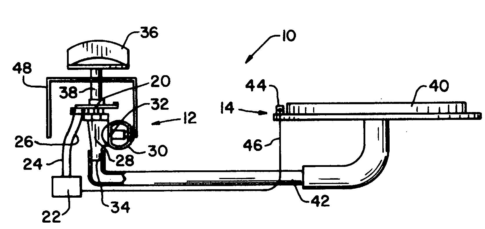
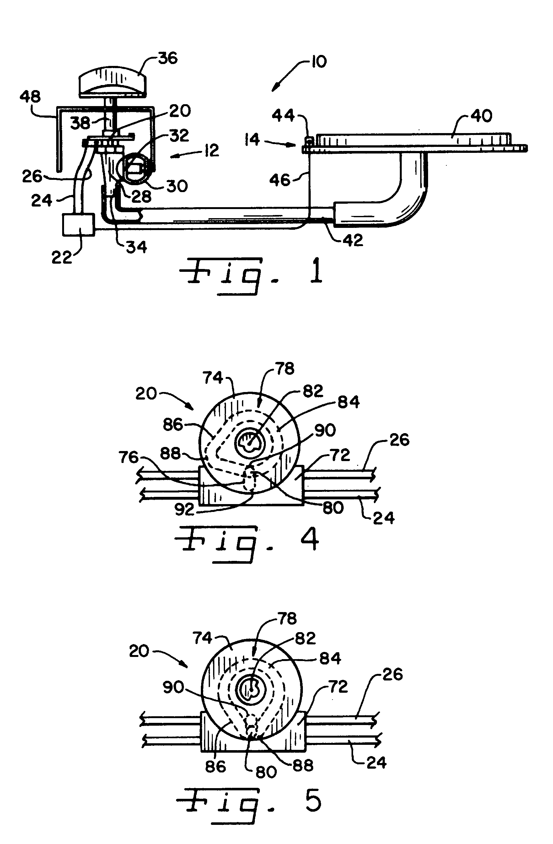
[0027]Referring now more specifically to the drawings and to FIG. 1 in particular, a gas fired appliance 10 is shown having a control assembly 12 in accordance with the present invention for operating a gas burner assembly 14. Control assembly 12 regulates gas flow to burner assembly 14 and initiates an ignition spark to ignite the gas at burner assembly 14 when the flow of gas is initiated.
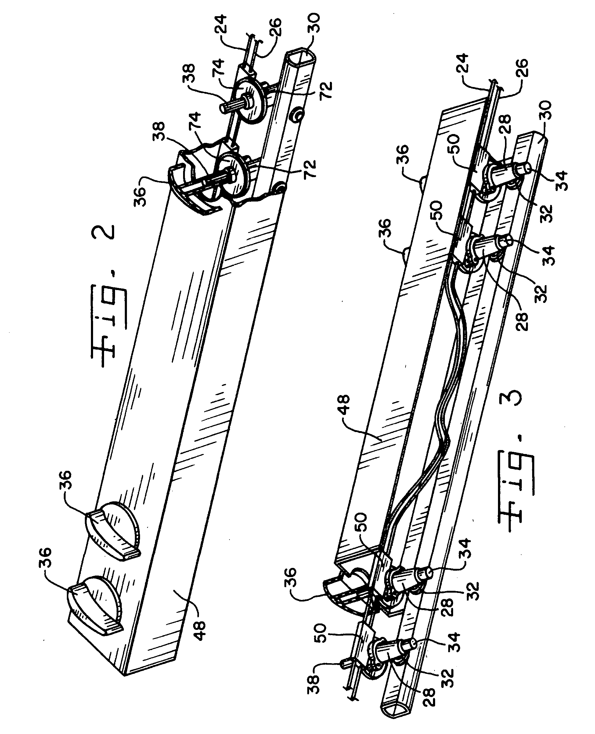
[0028]Control assembly 12 includes a reed switch 20 operatively connected to an electronic ignition module 22 by main conductors 24, 26. Control assembly 12 further includes a known gas valve 28 for controlling flow of gas from a gas manifold 30 to burner assembly 14, and includes a gas valve inlet 32 in flow communication with manifold 30 and a gas valve outlet 34 in flow communication with burner assembly 14. Reed switch 20 and gas valve 28 are controlled jointly by rotation of a control knob 36 connected to, for rotation of a valve shaft 38. Rotation of shaft 38 operates reed switch 20, as wil...
PUM
 Abstract
Description
Claims
Application Information