Adapter Device

a technology for adapters and electrosurgical elements, applied in the field of adapters for electrosurgical instruments, can solve the problems of costly and considerable organizational effort, and achieve the effects of easy replacement, easy assembly and disassembly of components, and reduced complexity of fitting adapters to electrosurgical elements

Active Publication Date: 2008-01-03
ERBE ELEKTROMEDIZIN GMBH
View PDF9 Cites 4 Cited by
  • Summary
  • Abstract
  • Description
  • Claims
  • Application Information

AI Technical Summary

Benefits of technology

[0012] In one embodiment the insulating portion is firmly connected to the electrically conductive portion. Hence, the complexity of fitting the adapter device to the electrosurgical element can be minimized because the adapter device can be fitted onto the electrosurgical instrument in one single operation.
[0013] The insulating portion and the electrically conductive portion are preferably capable of being connected to one another. If it is intended to produce the insulating portion and the electrically conductive portion as independent components, these can be replaced easily, for example if they have been damaged. However, a screwable connection ensures a reliable connection when the portions are fitted together.
[0014] In a further embodiment, the insulating portion and the electrically conductive portion can be connected to one another by means of a plug connection. The plug connection ensure particularly easy assembly and disassembly of the components so as to ensure fast and easy replacement of one single component.
[0015] The portions are preferably configured so that, when fitted, they are at least at such a distance from the sections of the power connection element to rule out tilting during assembly. End welding of the electrically conductive section and electrically conductive portion then ensures reliable arresting of the adapter and establishes electrical contact.

Problems solved by technology

Problems are caused by the fact that instruments with different shank diameters are manufactured on two different production lines and, for example, the single parts needed for production have to be stocked completely.
The realization of differing production processes, however, calls for a considerable organizational effort and is costly.

Method used


Image

  • Adapter Device
  • Adapter Device
  • Adapter Device

Examples


Embodiment Construction

[0023] In the following description, the same reference numbers are used to denote identical parts and those that have an identical effect.

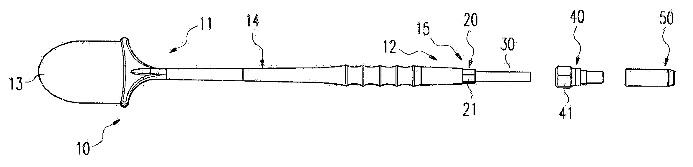
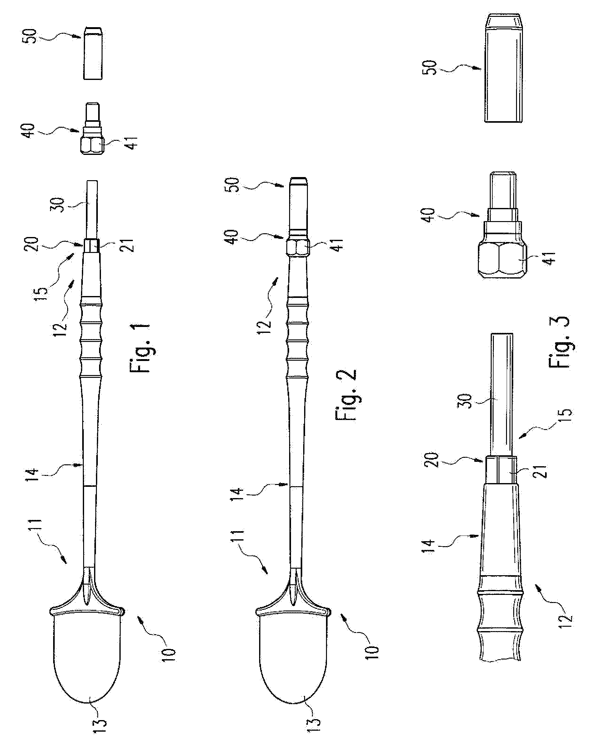
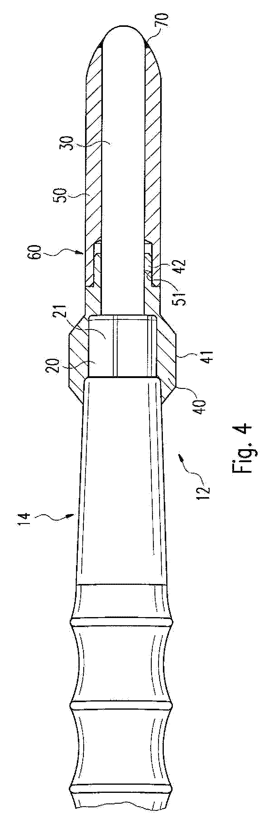
[0024]FIG. 1 shows an electrosurgical instrument 10 in an embodiment whereby the instrument 10 comprises an electrode 13 at one distal end. The electrode 13 is configured on a shank 14 of the electrosurgical instrument 10. A power connection element 15 is provided on one proximal end 12 of the electrosurgical instrument 10. The power connection element 15 consists of an insulating section 20 and an electrically conductive section 30. The insulating section 20 comprises a hexagonal part 21.

[0025] Commercially available electrosurgical instruments with monopolar electrodes are configured with a shank diameter of 2.35 mm or 4.00 mm. In FIG. 1, the electrosurgical instrument 10 is shown with a shank diameter of 2.35 mm. The power connection element 15 is designed accordingly. To provide the illustrated instrument 10 with a power connection element ...


PUM


Abstract

An adapter is provided for a power connection element between a handle and an electrosurgical instrument to be attached to it. This provides an adapter that makes it possible to reduce organizational effort and costs in the production of electrosurgical instruments with monopolar electrodes. To this end, the adapter includes an insulating portion for adapting an insulating section of the power connection element and an electrically conductive portion for adapting at least one electrically conductive section of the power connection element. The insulating portion and the electrically conductive portion are configured in such a way that the insulating section and the electrically conductive section have their dimensions increased.

Description

CROSS-REFERENCE TO RELATED APPLICATIONS [0001] This application is a Section 371 of International Application No. PCT / EP2005 / 007682, filed Jul. 14, 2005, which was published in the German language on Jan. 26, 2006, under International Publication No. WO2006 / 008072 A3, the disclosure of which is incorporated herein by reference.BACKGROUND OF THE INVENTION [0002] The invention relates to an adapter for an electrosurgical instrument and in particular for a power connection element located between a handle and an electrosurgical instrument adapted to be fastened to it. [0003] For many years now, electrosurgical instruments have been in use in high-frequency surgery to coagulate or cut biological tissue. In the case of coagulation, a high-frequency current is passed through the tissue under treatment so that it contracts as a result of protein coagulation and dehydration, sealing vessels and making it possible to arrest bleeding. An increase in the current density permits complete separa...

Claims


Application Information

Patent Timeline
Patent Type & Authority Applications(United States)
IPC IPC(8): A61B18/18
CPCA61B2018/00178A61B18/14
Inventor HAGG, MARTINSCHNITZLER, UWE
Owner ERBE ELEKTROMEDIZIN GMBH
Why Eureka
Try Eureka