Method of processing time distribution in real time operating system

a real-time operating system and processing time technology, applied in the field of real-time operating system processing time distribution, can solve the problems of increasing complexity of software, poor processing efficiency, and increasing software complexity, and achieve the effect of efficient execution of dead-line-free processing

Inactive Publication Date: 2008-01-03
PANASONIC CORP
View PDF3 Cites 13 Cited by
  • Summary
  • Abstract
  • Description
  • Claims
  • Application Information

AI Technical Summary

Benefits of technology

[0010]Therefore, a main object of the present invention is to provide a method of efficiently executing a dead-line-free processing while guaranteeing the completion of a processing having the dead line within a dead line.

Problems solved by technology

Further, a scale of software is becoming larger and the software is increasingly complicated as the technology advances, and it is now indispensable to use the real time operating system.
In the foregoing case, however, an execution time of an idle task that is not effectively processed by a CPU is increased, which results in a poor processing efficiency.
Accordingly, the processing efficiency is poor because the idle task is allowed to operate only between the periods T1-T2, T3-T4 and T5-T6.
However, the conventional technology is disadvantageous in that it can only be judged if the first processing group A is completed by the dead line in the system including the first processing group A having the dead line for the processing to be completed and the second processing group B without any dead line for the processing to be completed, and it is not possible to guarantee the improvement of the processing efficiency of the second processing group B. In other words, it is not possible to guarantee the dead line of the first processing group A while efficiently distributing the processing time Of the second processing group B.

Method used


Image

  • Method of processing time distribution in real time operating system
  • Method of processing time distribution in real time operating system
  • Method of processing time distribution in real time operating system

Examples


embodiment 1

Preferred Embodiment 1

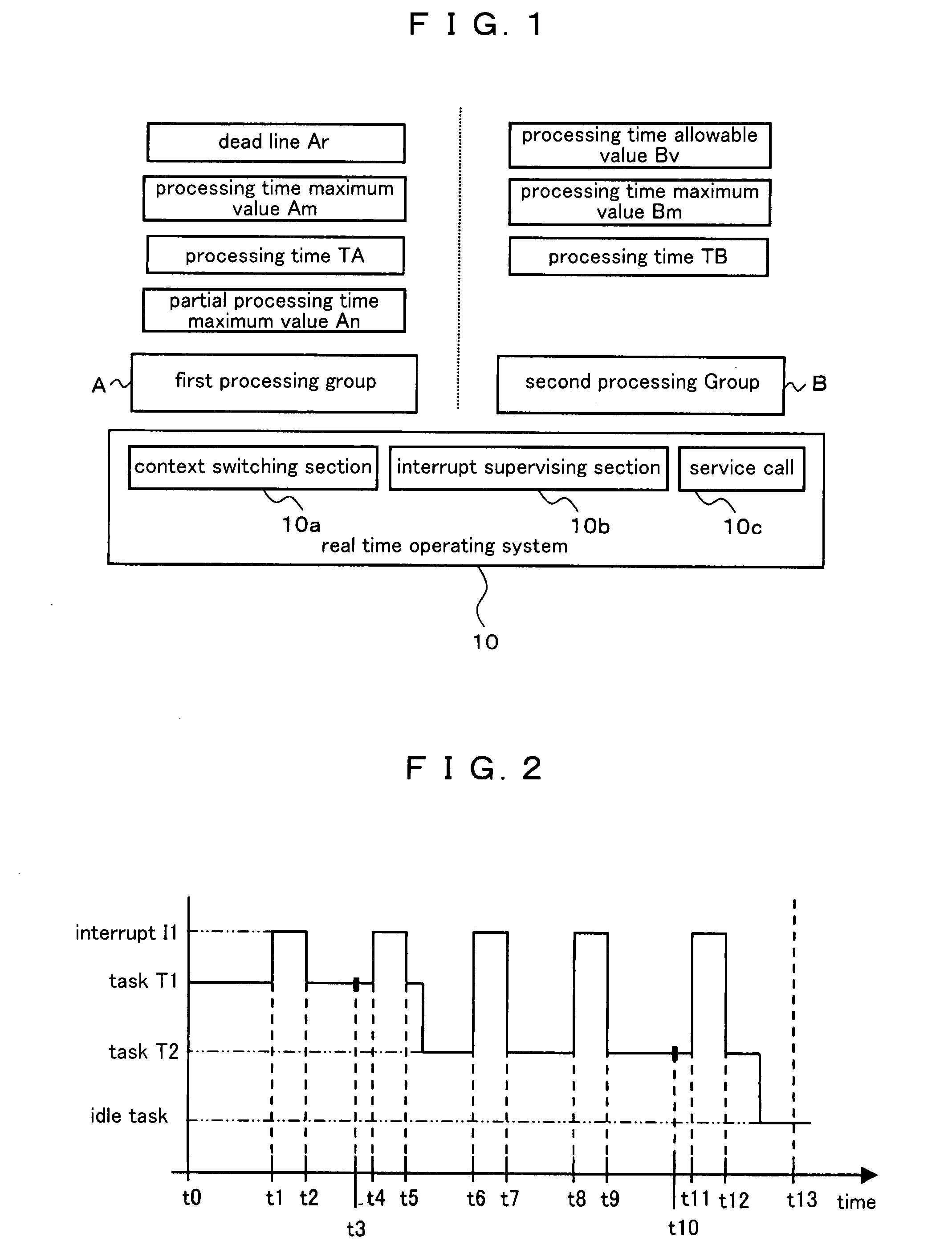
[0046]FIG. 1 shows a system configuration of a method for distributing processing time in a real time operating system according to a preferred embodiment 1 of the present invention. In the configuration according to the present preferred embodiment, a first processing group A having a dead line leading up to completion of the processing and a second processing group B without any dead line leading up to completion of the processing are operated on a real time operating system 10.

[0047]The first processing group A supervises:[0048]dead line Ar set previously as a maximum tolerance value of time necessary for processing of the first processing group A to be completed;[0049]maximum value of the processing time necessary from start-up to completion of the processing of the first processing group A[0050]processing time TA from the start-up of the processing of the first processing group A; and[0051]maximum value of a partial processing time that is a maximum value ...

embodiment 2

Preferred Embodiment 2

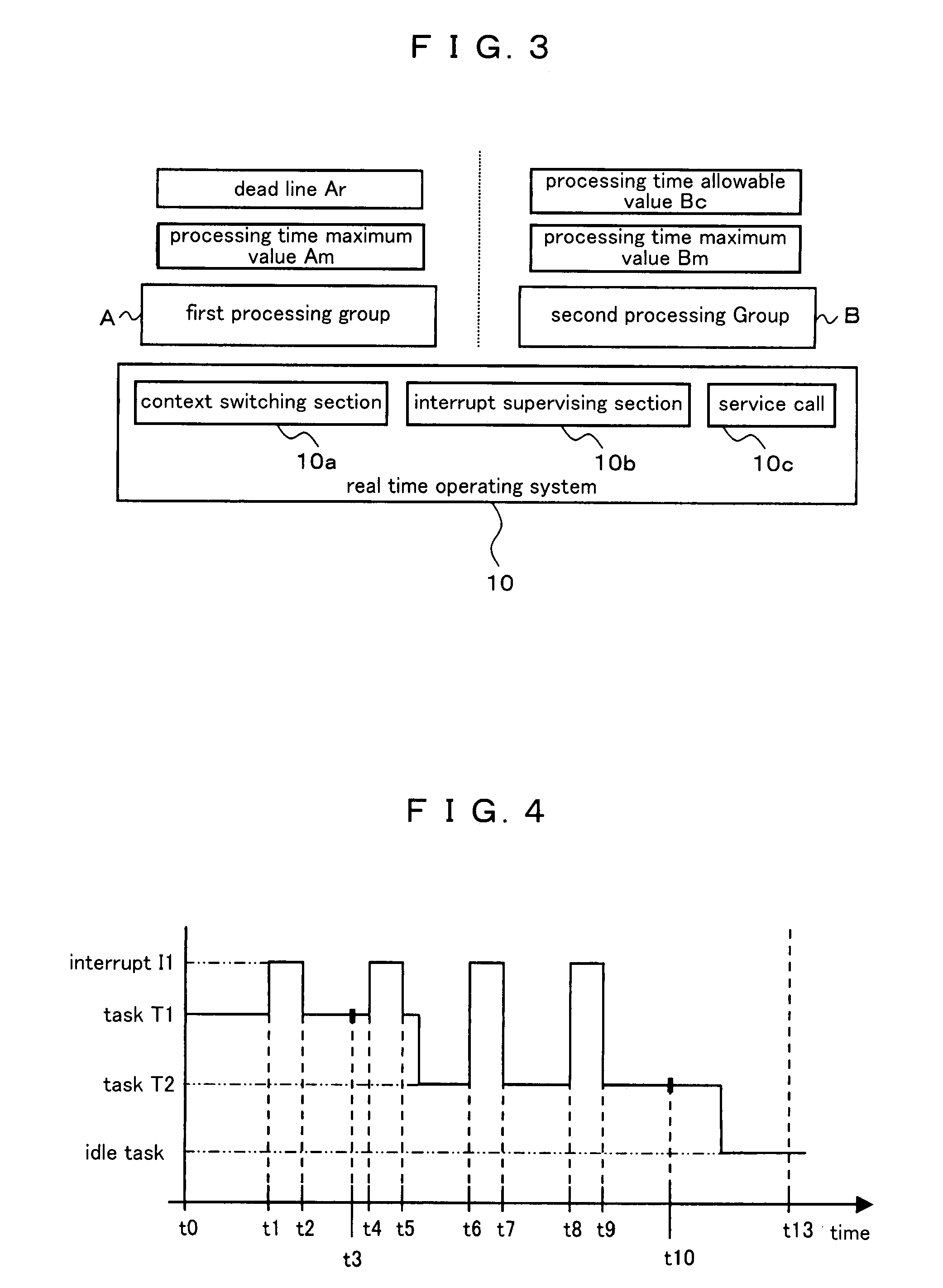
[0076]In the preferred embodiment 1, the time difference between the dead line Ar and the processing time maximum value Am (Ar−Am) of the first processing group A is set as the processing time allowable value Bv of the second processing group B. On the contrary, in a preferred embodiment 2 of the present invention, “processable number of times”, that is calculated from the time difference (Ar−Am), is set as a processing time allowable value Bc of the second processing group B.

[0077]FIG. 3 shows a system configuration of a method for distributing a processing time in a real time operating system according to the preferred embodiment 2. In the configuration according to the present preferred embodiment, a first processing group A having a dead line leading up to completion of the processing and a second processing group B without any dead line leading up to completion of the processing are operated on a real time operating system 10.

[0078]The first processing gro...

embodiment 3

Preferred Embodiment 3

[0093]In the case of the preferred embodiment 2 wherein the processable number of times described above is used as the processing time allowable value, the actual processing time may be shorter than the processing time maximum value depending on a system, for example, in a cache system. More specifically, even though the second processing group B is made to be in the interrupt-allowable state again after the second processing group B is implemented as many times as the processing time allowable value Bc that is previously calculated, the dead line Ar of the first processing group A may be guaranteed. Such a situation is generated when the processable number of times is used as a judgment reference. More specifically, such a situation may be generated because a remainder is possibly generated when the processable number of times is calculated in the formula of (Ar−Am)÷Bm.

[0094]In a preferred embodiment 3 of the present invention, therefore, it is judged whether ...


PUM


Abstract

A processing time necessary from start by end of processing of a first processing group and a second processing group is calculated. A time difference between a dead line previously set as a maximum tolerance value of the processing time necessary by completion of the processing of the first processing group, and the calculated processing time is calculated. An initial value of a processing time allowable value of the second processing group is calculated based on the time difference. The processing time allowable value is updated at the time of processing in the operating system. It is judged whether or not the second processing group can be executable based on the updated processing time allowable value.

Description

BACKGROUND OF THE INVENTION[0001]1. Field of the Invention[0002]The present invention relates to a method of processing time distribution in a real time operating system, more specifically to a technology for improving a processing efficiency in a whole real time operating system including a first processing group where there is a time restriction until completion of the processing and a second processing group without any restriction until completion of the processing.[0003]2. Description of the Related Art[0004]An installation system is a computer system installed in various machines and devices so as to control them, and a number of technical fields where they are applied is expanded rapidly in recent years. Further, a scale of software is becoming larger and the software is increasingly complicated as the technology advances, and it is now indispensable to use the real time operating system.[0005]As a key indicator of the real time operating system, it is an important issue to g...

Claims


Application Information

Patent Timeline
Patent Type & Authority Applications(United States)
IPC IPC(8): G06F17/00
CPCG06F9/4887
Inventor KOBAYASHI, KEITAITO, YUSUKEICHINOSE, NAOYAMATSUSHIMA, YOUKOMORITA, RYOKOSASAOKA, TOSHIO
Owner PANASONIC CORP
Why Eureka
Try Eureka