Surface mounting structure for electronic component

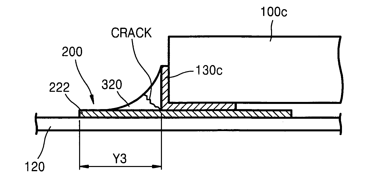
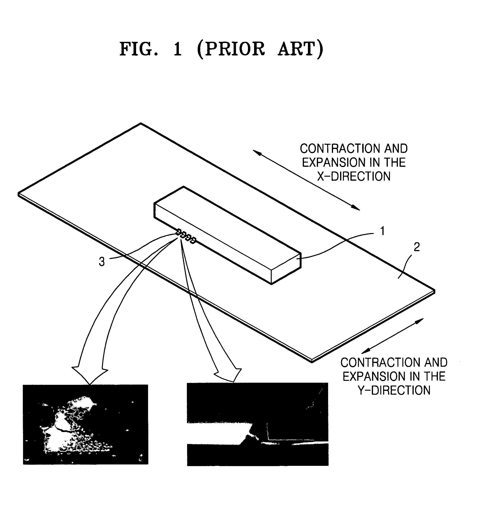
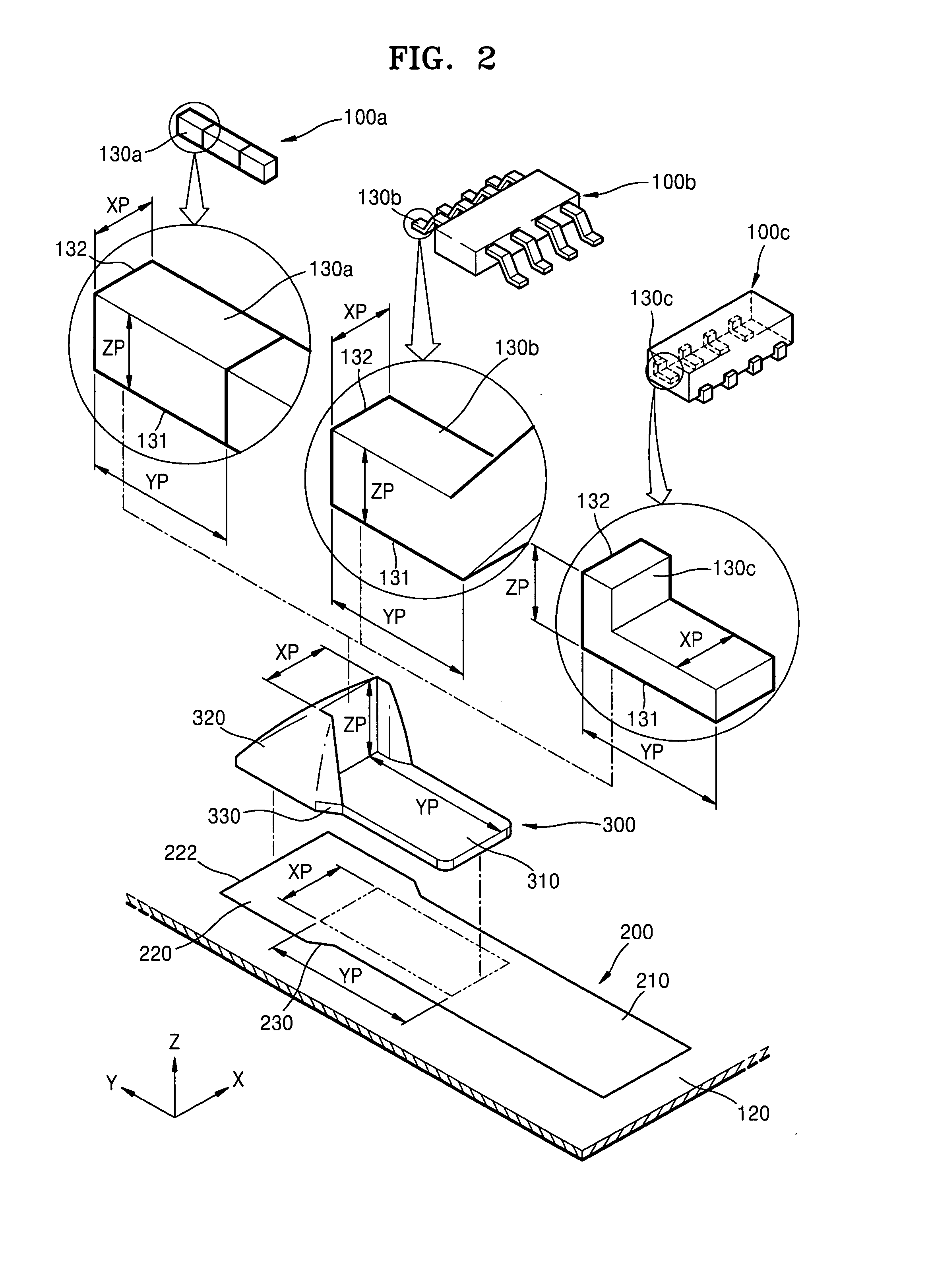
a technology for mounting structures and electronic components, applied in the direction of printed circuit aspects, sustainable manufacturing/processing, final product manufacturing, etc., can solve the problems of cracks in the fillet, circuit boards mounted in such devices becoming more miniaturized, etc., to prevent the generation and growth of cracks

Inactive Publication Date: 2008-01-10
SAMSUNG ELECTRONICS CO LTD
View PDF0 Cites 4 Cited by
  • Summary
  • Abstract
  • Description
  • Claims
  • Application Information

AI Technical Summary

Benefits of technology

[0009]An aspect of the present invention is to address at least the above problems and / or disadvantages and to provide at least the advantages described below. Accordingly, an aspect of the present invention is to provide a surface mounting structure that can prevent generation and growth of a crack when stress concentrates on a soldering portion because of discrepancies in thermal expansion and contraction between a circuit substrate and an electronic component caused by different coefficients of thermal expansion.

Problems solved by technology

The circuit boards mounted in such devices are also becoming more miniaturized.
The thermal stresses produced by the different coefficients of thermal expansion of the electronic component 1 and the circuit board 2 are concentrated on the fillet where the circuit board 2 and the electronic component 1 are coupled together, and eventually cause a crack in the fillet.

Method used


Image

  • Surface mounting structure for electronic component
  • Surface mounting structure for electronic component
  • Surface mounting structure for electronic component

Examples


Embodiment Construction

[0027]The matters defined in the description such as a detailed construction and elements are provided to assist in a comprehensive understanding of the exemplary embodiments of the invention and are merely exemplary. Accordingly, those of ordinary skill in the art will recognize that various changes and modifications of the exemplary embodiments described herein can be made without departing from the scope and spirit of the invention. Also, descriptions of well-known functions and constructions are omitted for clarity and conciseness.

[0028]The present invention will now be described more fully with reference to the accompanying drawings, in which exemplary embodiments of the invention are shown. In the drawings, the thicknesses of layers and regions are exaggerated for clarity. Also, the terms used herein are defined in accordance with the functions of the present invention. Thus, the terms may vary depending on the intent and usage. That is, the terms used herein must be interpret...


PUM


Abstract

A surface mounting structure for an electronic component is provided. A lead of the electronic component is soldered to a land including a first land portion to which a bottom surface of the lead is soldered, and a second land portion having a greater width than the first land portion and to which an end portion of the lead is soldered. The structure ensures stability and reliability while utilizing a small area of a circuit board.

Description

CROSS-REFERENCE TO RELATED PATENT APPLICATION[0001]This application claims the benefit under 35 U.S.C. §119(a) of Korean Patent Application No. 10-2006-0062436, filed on Jul. 4, 2006, in the Korean Intellectual Property Office, the entire disclosure of which is hereby incorporated by reference.BACKGROUND OF THE INVENTION[0002]1. Field of the Invention[0003]The present invention relates to a surface mounting structure for an electronic component. More particularly, the present invention relates to a surface mounting structure for attaching a lead of an electronic component to a land formed on a circuit board by soldering.[0004]2. Description of the Related Art[0005]With the rapid development of information technology, miniaturized and enhanced devices such as mobile electronic devices are continuously emerging. The circuit boards mounted in such devices are also becoming more miniaturized. To mount various kinds of electronic components within the small area of these miniaturized cir...

Claims


Application Information

Patent Timeline
Patent Type & Authority Applications(United States)
IPC IPC(8): H01L23/02
CPCH05K1/111H05K3/3421H05K3/3442H05K2201/10689H05K2201/09727H05K2201/10636H05K2201/09381Y02P70/50H05K3/30
Inventor NAGATANINI, KANAME
Owner SAMSUNG ELECTRONICS CO LTD
Why Eureka
Try Eureka