Supercharge Your Innovation With Domain-Expert AI Agents!

Air spring damper module

a damper module and air spring technology, applied in the direction of shock absorbers, mechanical equipment, transportation and packaging, etc., can solve the problems of reduced damping power, high load on high load on the closure of the outer tube of the shock absorber, so as to reduce the load and reduce the load

Active Publication Date: 2008-01-10
CONTITECH LUFTFEDERSYST
View PDF6 Cites 5 Cited by
  • Summary
  • Abstract
  • Description
  • Claims
  • Application Information

AI Technical Summary

Benefits of technology

[0007] It is an object of the invention to provide a constructively simplified air spring damper module of the kind described above wherein the closure of the shock absorber is not touched by the roll-off piston even at high loads while at the same time providing a simple assembly and disassembly of the roll-off piston and the shock absorber.
[0009] The closure of the shock absorber remains free of forces of the air spring in all loading situations because of the support of the pipe on the annular flange of the shock absorber. Especially when the closure of the shock absorber is configured with an interlocking flanged connection, this solution ensures a largest possible protection of this flanged connection. A stable support of the piston against transverse forces is achieved via the suitable selection of the inner diameter of the pipe. Furthermore, during operation, a portion of the air spring support forces are directed via the pipe directly to the shock absorber and so relieve the sensitive construction of the piston skirt and piston base.
[0011] The advantages of this arrangement are the avoidance of a double fit as well as relative movements of the pipe to the shock absorber.
[0015] The advantage of this arrangement is that the stop buffer is guided by the concave buffer stop surface. In this way, the danger of buckling of the air spring damper module, for example, by an off center loading, is reduced.

Problems solved by technology

It is disadvantageous that such roll-off pistons are complex, heavy and correspondingly cost intensive.
In this solution, the closure of the outer tube of the shock absorber is subjected to very high loadings.
If the closure is configured as an interlocking flanged connection, leaks and decreased damping power can occur because of the special sensitivity of the interlocking flanged connection with respect to mechanical damage or alternating bending loads.
A disassembly of the shock absorber, for example, for the purpose of exchange, is made very difficult or impossible because of the fixedly mounted protective cover.

Method used


Image

  • Air spring damper module
  • Air spring damper module
  • Air spring damper module

Examples


Embodiment Construction

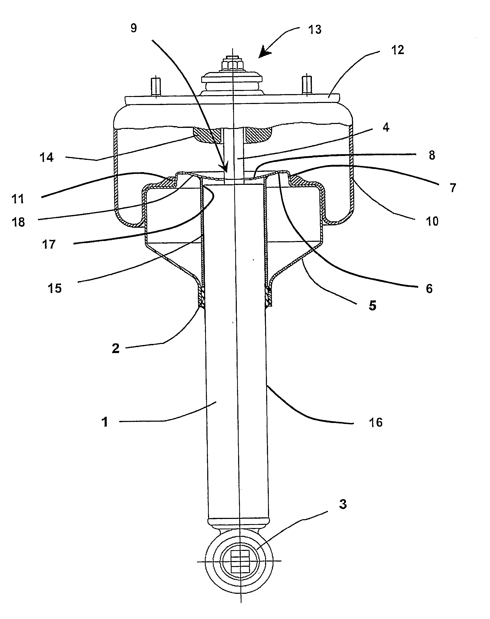
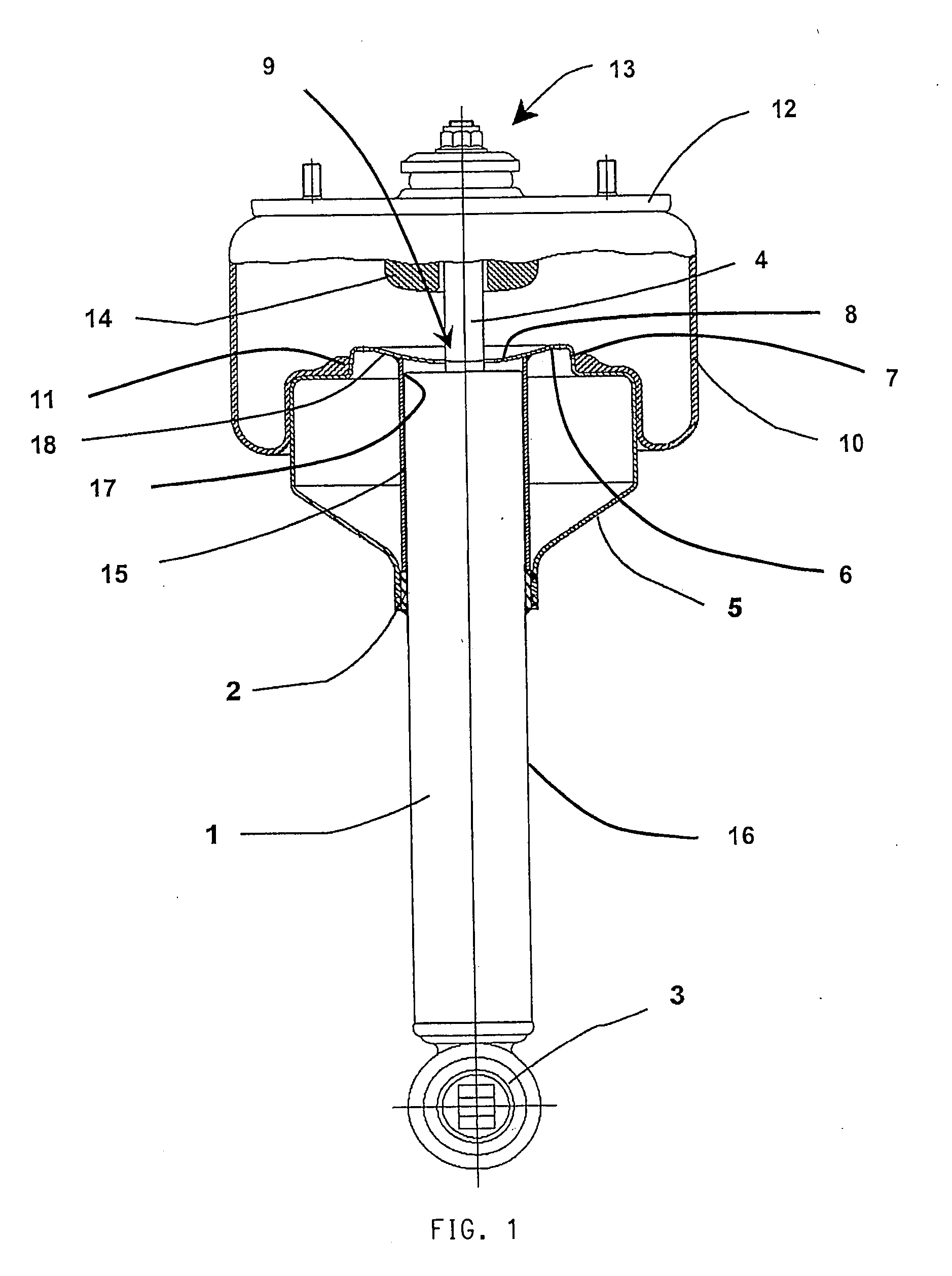
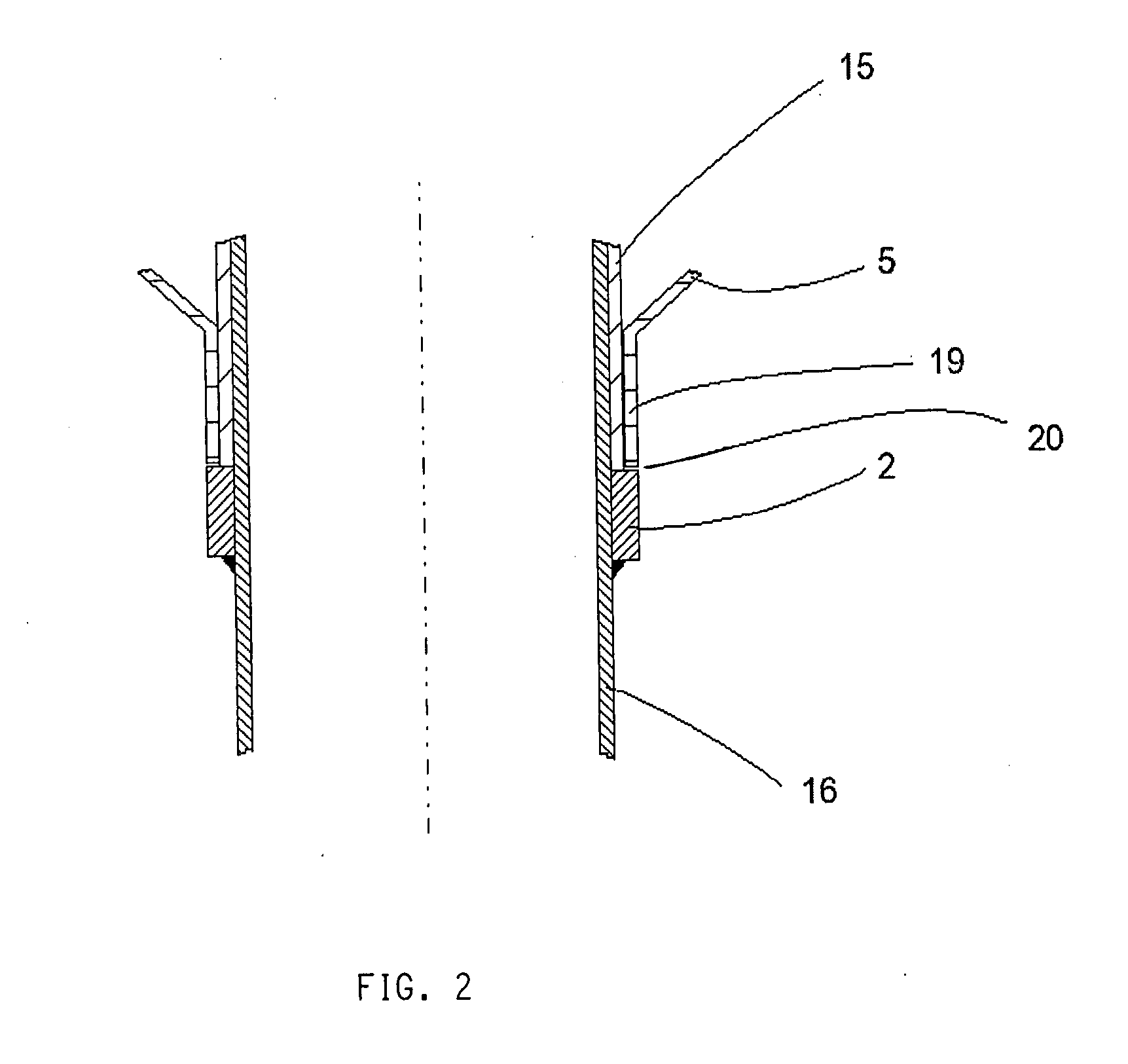
[0019] The air spring damper module shown in FIG. 1 includes a shock absorber 1 having an annular flange 2, an eye 3 for attaching the shock absorber 1 to a body of a commercial vehicle chassis and a damper rod 4. The body and the chassis of the commercial vehicle are not shown. A roll-off piston 5 is placed on the upper end of the shock absorber 1. The roll-off piston 5 is supported on the annular flange 2. The roll-off piston 5 includes a piston cover 6. A conical seat 7 is arranged centrally in the piston cover 6. The conical seat 7 has a perforated buffer stop surface 8 which is arcuately concave in the piston interior. The damper rod 4 is guided via the hole 9 through the buffer stop surface 8.

[0020] A rolling-lobe flexible member 10 is placed on the conical seat 7 and this flexible member rolls off on the roll-off piston5 and, with a sealing bead 11, forms an air-tight connection between roll-off piston 5 and air spring flexible member 10. The air spring flexible member 10 is...


PUM


Abstract

The invention relates to an air spring damper module including a shock absorber (1) and a roll-off piston (5) which is pushed over the upper end of the shock absorber with an opening in the piston base with the piston base being supported on the outer tube (16) of the shock absorber via an annular flange (2). A pipe (15) is centrally fixed to the inner surface of the piston cover (6) and engages around the shock absorber (1) in the mounted state and also is supported on the annular flange (2) of the shock absorber (1). The inner surface of the piston cover and the upper closure of the shock absorber are spaced apart by a gap.

Description

CROSS REFERENCE TO RELATED APPLICATIONS [0001] This application is a continuation-in-part application of PCT / EP 2005 / 012275, filed Nov. 16, 2005, designating the United States and claiming priority from German application no. 10 2004 060 466.5, filed Dec. 16, 2004, the entire content of both applications being incorporated herein by reference.FIELD OF THE INVENTION [0002] The invention relates to an air spring damper module including: a shock absorber having: an outer tube having a closure at an upper end of the shock absorber with the upper end facing upwardly in the built-in position and an annular flange fixed to the outer tube and spaced from the upper end of the shock absorber; and, a damper rod; a roll-off piston mounted on the upper end of the shock absorber with the roll-off piston having: a piston cover with an outer surface and an inner surface and with a piston base having a central opening; an air spring flexible member mounted and fixed on the roll-off piston, the air s...

Claims


Application Information

Patent Timeline
IPC IPC(8): B60G11/27F16F9/02
CPCF16F9/084F16F9/05
Inventor STAHMER, REINHARD
Owner CONTITECH LUFTFEDERSYST
Features
  • R&D
  • Intellectual Property
  • Life Sciences
  • Materials
  • Tech Scout
  • Unparalleled Data Quality
  • Higher Quality Content
  • 60% Fewer Hallucinations
Learn More