System and method for deliverying an agglomeration of solid beads and cement to the interior of a bone in order to form an implant within the bone

a technology of liquid state cement and solid beads, which is applied in the field of system and method for delivering solid beads and liquid state cement for implantation into the interior of the bone, can solve the problems of reducing the effect of balloon-like devices, and reducing the quality of life, so as to prevent the movement of the implant, prevent the extravasation of the fluent material, and ensure the stability of the bony structur

Inactive Publication Date: 2008-01-10
SPINAL VENTURES
View PDF11 Cites 110 Cited by
  • Summary
  • Abstract
  • Description
  • Claims
  • Application Information

AI Technical Summary

Benefits of technology

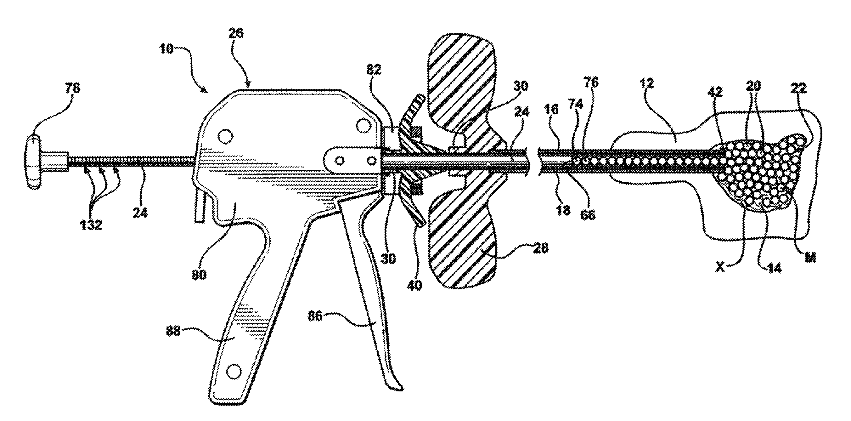
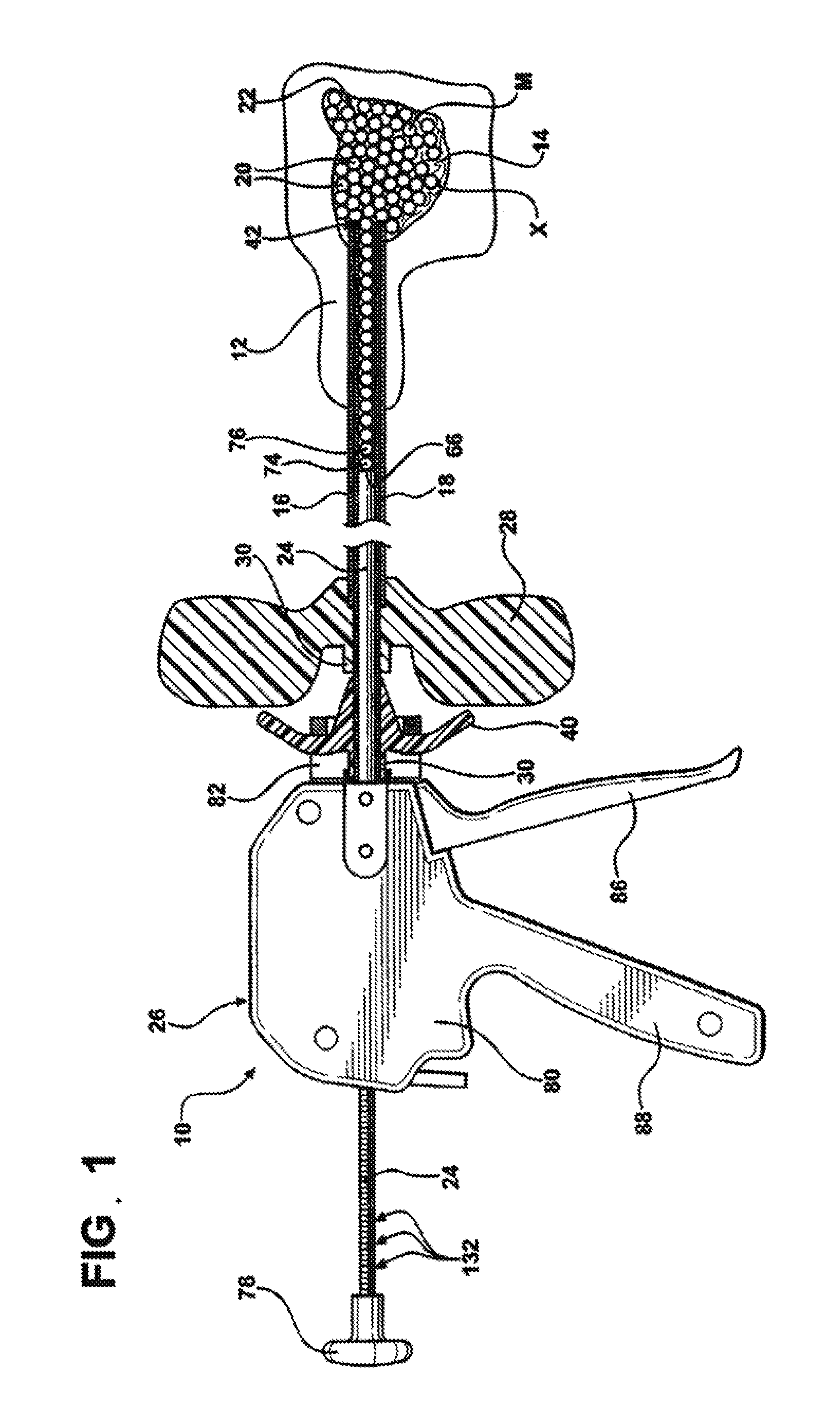
[0017] By delivering the beads under the force of the push rod, the fluent material is transported by the beads and enters into the interior of the vertebral body under a low pressure. This low pressure delivery of the fluent material prevents extravasations which can result from delivering the fluent material under a high pressure. Additionally, amounts of the beads and the fluent material delivered can be highly controlled to ensure adequate stabilization of the bony structure of cancellous bone present within the vertebral body thereby preventing motion of the implant within the vertebral body. The system also provides the user with flexibility in that the beads and the fluent material can be loaded into the delivery cannula and delivered to the interior of the vertebral body using a variety of loading and delivery systems.

Problems solved by technology

Typically, these vertebrae fail at an anterior cortical wall causing a wedge shaped collapse of the vertebra.
Fractures can be painful for the patient typically causing a reduced quality of life.
These balloon-like devices have been known to fail during inflation due to the high inflation pressures, thin balloon membranes required to fit into the percutaneous passage, and sharp tools or bony structures piercing the membranes.
This action can occur in an uncontrollable manner where the user cannot influence the direction of the flow.
Other vertebroplasty procedures do not employ balloon-type devices to create a void space in the vertebra into which the cement is flowed.
Again, due to the high pressure under which this cement is introduced into the bone, the cement ill flow along the path of least resistance.
In some instances this leads to undesirable leaking or extravasations outside of the vertebral body.
However, occasionally complications have arisen as a result of these cement leaks outside of the vertebral body.
These side effects can result in loss of neurological function or even result in a pulmonary embolism.
Another limitation of the current pressure delivery system is the difficulty of visualizing the flowable materials using a fluoroscope.
As one can appreciate, the inability to see thin flow fronts can mislead the practitioner into applying more pressure to deliver more flowable materials, even when the thin flow fronts are leaking outside the vertebral body and into undesirable locations.
A shortcoming of these systems is the lack of complete stabilization of the bony structure and the lack of a permanent fixation of the implant M to the bone.
It is believed that motion of a bony structure of cancellous bone within the vertebral body may result in pain to the patient.
Once the wafer stack is formed, the bone cement can be delivered into the vertebral body around the wafer stack to lock the wafers together and form a stable implant M. The wafer stack provides support on upper and lower sides of the vertebral body, but may not provide uniform support on all sides.
Also, Johnson et al. does not disclose how much bone cement is delivered and / or whether enough is delivered to stabilize the bony structure of cancellous bone within the vertebral body.
Furthermore, this delivery occurs through relatively little control of the flow of pressurized bone cement during delivery, much like as described above.

Method used


Image

  • System and method for deliverying an agglomeration of solid beads and cement to the interior of a bone in order to form an implant within the bone
  • System and method for deliverying an agglomeration of solid beads and cement to the interior of a bone in order to form an implant within the bone
  • System and method for deliverying an agglomeration of solid beads and cement to the interior of a bone in order to form an implant within the bone

Examples


example 1

[0134] If the volume of the cement 22 delivered from the delivery cannula 18 is equal to the final volume available for the cement 22 in the interstitial gaps provided by the beads 20 in the final implant M, then cement 22 does not have to be delivered by displacement (pressure), but is transported or carried solely by the beads 20. Therefore, the cement 22 experiences no pressurization in the final implant M. In this instance, the likelihood of the cement 22 leaking outside of the implant M is reduced. This condition is illustrated in FIG. 26A. This is advantageous for percutaneous treatment of vertebral compression fractures since the likelihood of cement 22 leaking from the vertebral body 12 due to pressurization in the cement 22 would be minimized.

example 2

[0135] If the volume of the cement 22 delivered from the delivery cannula 18 is greater than the final volume available for the cement 22 in the interstitial gaps provided by the beads 20 in the final implant M, then at least a portion of the cement 22, i.e., the volume of the cement 22 equal to the volume difference, must be delivered by displacement and / or transported by the beads 20. Therefore, the cement 22 experiences a positive pressure and it would be expected that this pressure in the cement 22 will attempt to move until it finds a state of equilibrium within its surroundings at the target site X. As illustrated in FIG. 26B, when there is a positive pressure on the cement 22 the cement 22 moves to an outer boundary or periphery of the implant M. In some cases, it may be desirable to provide some of the cement 22 at the outer boundary of the implant M to better secure the implant M in the target site X, to bond with cancellous bone 14 outside of the implant M, and the like. T...

example 3

[0136] If the volume of the cement 22 delivered from the delivery cannula 18 is less than the final volume available for the cement 22 in the interstitial gaps provided by the beads 20 in the final implant M, then the cement 22 does not have to be delivered by displacement, but may be transported solely by the beads 20. Therefore, the cement 22 experiences a theoretical negative pressure and not all of the interstitial spaces between the beads 20 in the target site X are filled with the cement 22, as illustrated in FIG. 26C. It may be desirable to provide an implant M that is loosely packed in the target site X such that a volume of interstitial spaces between the beads 20 is greater than the amount of the cement 22 delivered to the target site X. This may be advantageous to facilitate tissue in-growth in the void spaces.

[0137] Examples 1, 2, and 3 may be desirable for different applications. Each of the examples can be achieved by using the disclosed low pressure design principles...


PUM


Abstract

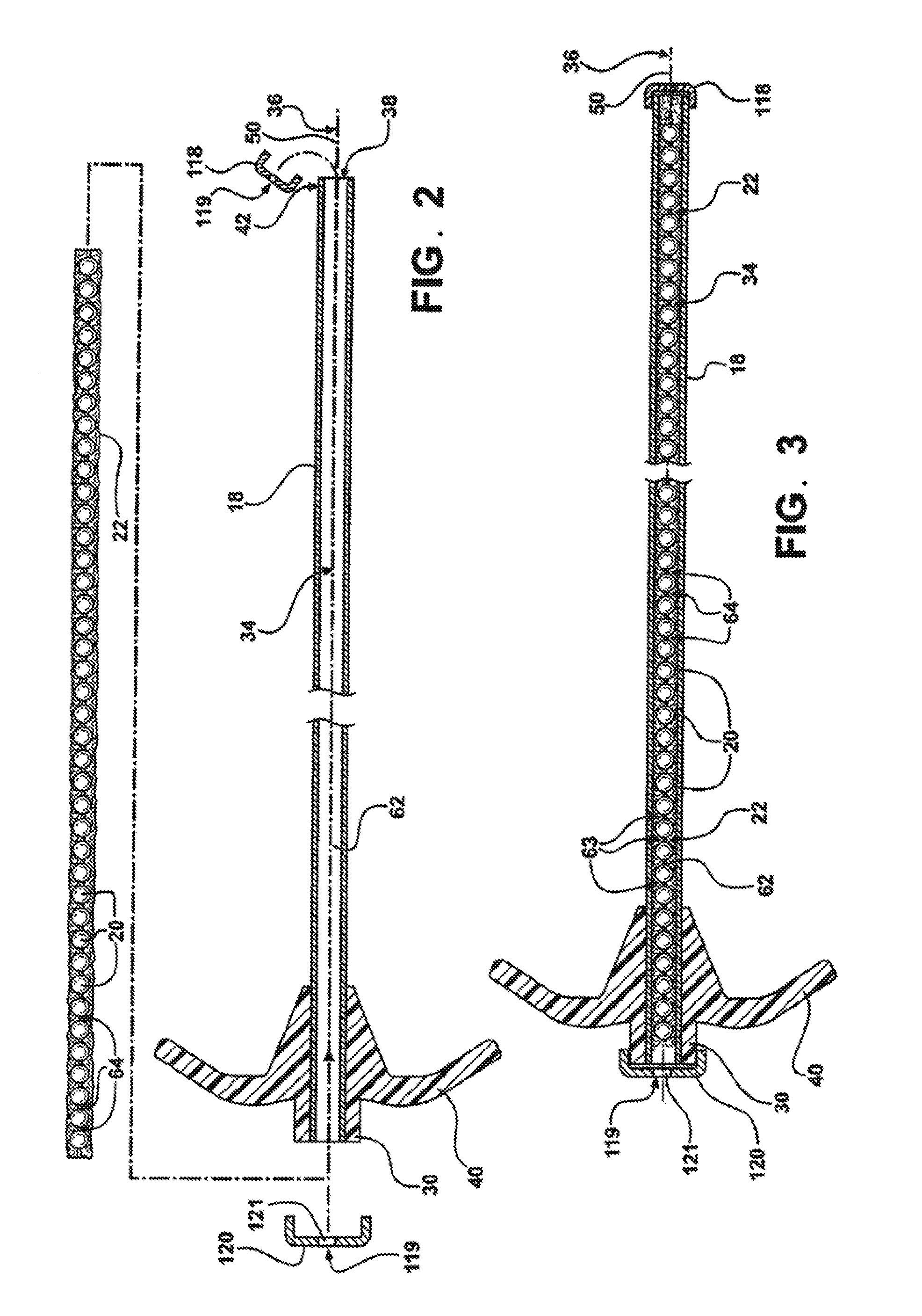
A system for forming an implant to stabilize an interior of a vertebral body is provided. The system includes a delivery cannula (18) in which there is an agglomeration of beads (20) and cement (22). A membrane is disposed over the open end of the cannula. When the agglomeration is discharged from the cannula it fills the membrane. The membrane thus forms the outer shell of the implant internal to the bone.

Description

CROSS REFERENCE TO RELATED APPLICATIONS [0001] This application claims the benefit of U.S. patent application Ser. No. 11 / 627,771 filed Jan. 26, 2007 which claims the benefit of U.S. Provisional Patent Application Ser. No. 60 / 762,779, filed on Jan. 27, 2006, and U.S. Provisional Patent Application Ser. No. 60 / 808,681, filed on May 26, 2006. Each of the foregoing applications are hereby incorporated by reference.FIELD OF THE INVENTION [0002] The invention generally relates to a system and a method for delivering a mixture, an agglomeration of solid beads and liquid-state cement for implantation into a bone. More particularly, this invention relates to a system and method for delivering the mixture of solids and cements so as to minimize the uncontrolled flow of cement out of the space into which it is delivered. BACKGROUND OF THE INVENTION [0003] Systems are well known in the art for delivering materials such as bone cement to a target site for medical treatment. One particular use o...

Claims


Application Information

Patent Timeline
Patent Type & Authority Applications(United States)
IPC IPC(8): A61M31/00
CPCA61B17/3472A61B17/7094A61B17/8822A61B17/8811A61B17/8816A61B17/7095A61B17/8805
Inventor HENNIGES, BRUCETYLER, DOUGHUYSER, RICHARDSMIT, KAREN
Owner SPINAL VENTURES
Why Eureka
Try Eureka