
Relation to Blind Bolting

a technology of blind bolting and threading, which is applied in the direction of washing machines, manufacturing tools, mechanical equipment, etc., can solve the problems of high dispersion of load, limited use in structural applications, and relatively high cost of bolts to manufactur

Active Publication Date: 2008-01-17
IRA SVENDSGAARD & ASSOC INC +1
View PDF1 Cites 8 Cited by
  • Summary
  • Abstract
  • Description
  • Claims
  • Application Information

AI Technical Summary

Benefits of technology

[0011]Said moveable member may prevent rotational movement of said protrusion relative to said socket when said moveable member is engaged across said interface.
[0018]In another aspect the invention envisages a bolt comprising:(i) an enlarged head portion at one end,(ii) a threaded tail portion at the end opposite said head,(iii) a major axis running the length of said bolt, and(iv) a protrusion extending from said threaded tail portion, said protrusion having a non-circular cross section transverse to said axis and having formed into its periphery a recess adapted to receive a moveable member on a tool to thereby prevent withdrawal of said protrusion from the tool.

Problems solved by technology

These have evolved over many years and may be suitable for limited structural applications.
However a major problem with bolts of that type is that the failure load has a high dispersion and hence the use in structural applications is limited.
Also these bolts are relatively expensive to manufacture.
The operation of threading and unthreading the bolt from the tool has been sometimes perceived by users as tedious, and the tool has in some cases been damaged by careless use.
Furthermore, the left hand thread provided in the previous invention will not restrain the bolt when undoing the nut hence making it difficult to undo the fasteners.

Method used


Image

  • Relation to Blind Bolting
  • Relation to Blind Bolting
  • Relation to Blind Bolting

Examples


Embodiment Construction

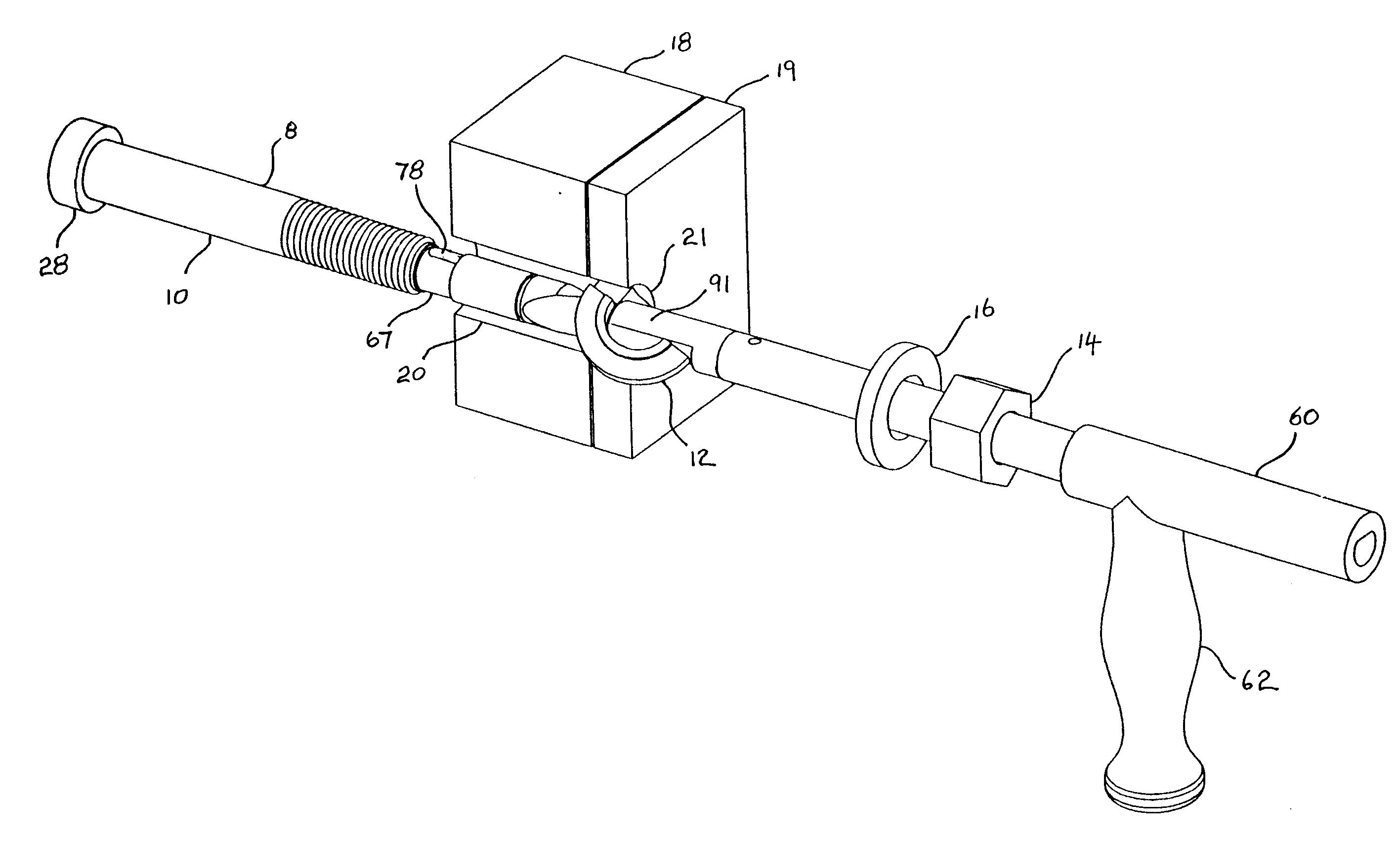
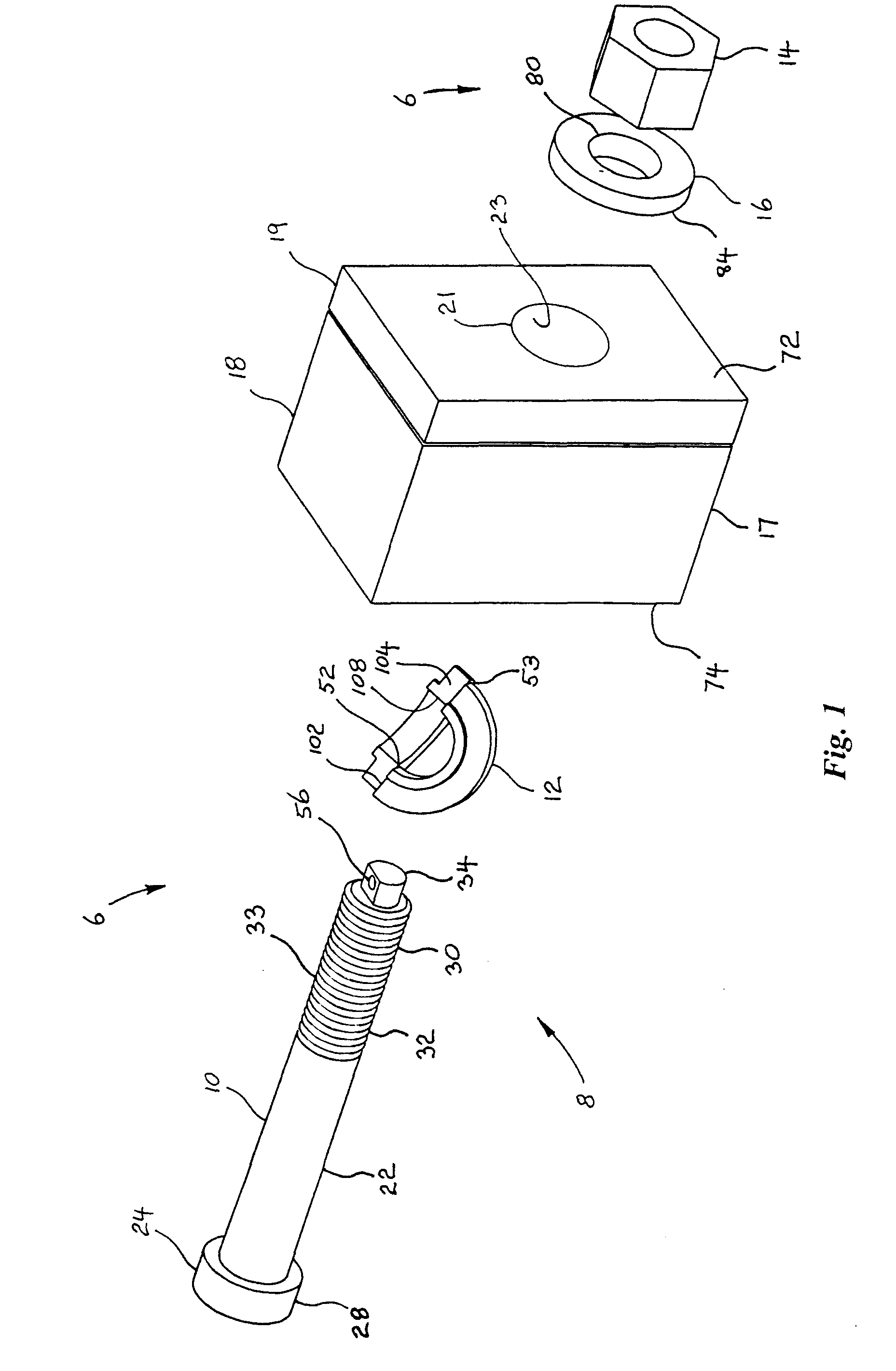
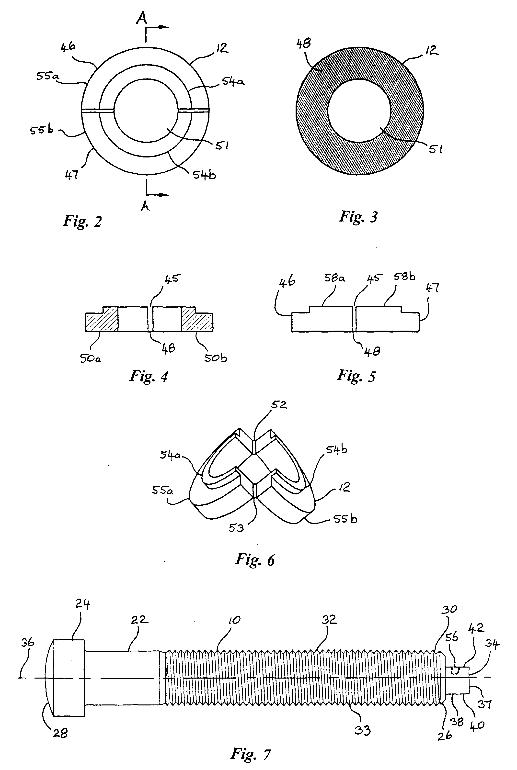
[0042]Referring to FIGS. 1 to 12, a fastener assembly 6 comprises a fastener 8, a nut 14 and washer 16. The fastener 8 consists of a bolt portion 10 and a round collar portion 12. The fastener joins two steel plates 18 and 19 (together comprising a substrate) by passing through holes 20 and 21 in them and being tensioned. FIG. 12 shows a diametral half of the assembled and tensioned fastener 8 extending through the plates 18 and 19 with the collar 12, washer 16 and nut 14 engaged.

[0043]The bolt 10 has a shank 22 with, at one end 24, an enlarged head 28 and, at the other end 26, a tail 30 which carries a thread 32 on a threaded portion 33 to suit the nut 14. The head 28 of the bolt 10 is a crown integrally formed with the shank 22. The head of the fastener 8 is thus the combination of the bolt head 28 and the collar 12. On the end of its tail 30 the bolt carries an axial protrusion 34 having a flat end face 37 and a peripheral surface 38. The peripheral surface 38 has a curved portio...


PUM

PropertyMeasurementUnit
heightaaaaaaaaaa
depthaaaaaaaaaa
thicknessaaaaaaaaaa

Abstract

A method of installing a threaded fastener from one side of a hole through a substrate. The fastener includes a collar and a bolt having a head, a threaded tail portion and a tool engagement portion extending from the tail. The method includes: (a) engaging the tool engagement portion with a bolt engagement portion of a tool (b) passing the bolt through to the far side of the hole and supporting it there by way of the tool, (c) passing the collar through the hole while supporting it with the tool; (d) assembling the bolt and collar to form the threaded fastener having a head larger than the hole; (e) engaging a nut to tighten the fastener; and (f) detaching the tool from the fastener. Separation of the bolt engagement portion and the tool engagement portion is prevented by a moveable member, which engages both portions.

Description

BACKGROUND TO THE INVENTION[0001]This invention concerns the use of threaded fasteners, particularly the field of bolts adapted to be installed entirely from one side of a hole. Such fasteners are commonly referred to as blind bolts.[0002]There is a need for threaded fasteners, particularly in structural steel applications, which can be installed from only one side of a hole so they may be used where the other side of the hole is inaccessible for some reason.[0003]One type of fastener, which can be installed from one side of a hole, includes those commonly called blind bolts. These have evolved over many years and may be suitable for limited structural applications. Examples are described in Australian patent specifications AU-A-67133 / 90, AU-A-20458 / 92 and AU-A-20279 / 95. However a major problem with bolts of that type is that the failure load has a high dispersion and hence the use in structural applications is limited. Also these bolts are relatively expensive to manufacture.[0004]...

Claims


Application Information

Patent Timeline
Patent Type & Authority Applications(United States)
IPC IPC(8): B23P11/00B23P17/00
CPCB25B13/48B25B13/481F16B5/02F16B43/006Y10T29/53704Y10T29/54Y10T29/49963Y10T29/49947Y10T29/49948Y10T29/53909
Inventor FERNANDO, SAMANWANG, JIANWENCOLEMAN, HUGH RICHARD
Owner IRA SVENDSGAARD & ASSOC INC
Learn More