Flexible leak detection system and method for double carcass hose

a leak detection system and flexible technology, applied in the direction of fluid leakage detection, fluid tightness measurement, instruments, etc., can solve the problems of single carcass hose leakage, systematic risk of oil leakage to the sea, and overpressure of the system

Active Publication Date: 2008-01-17
TRELLEBORG IND
View PDF79 Cites 8 Cited by
  • Summary
  • Abstract
  • Description
  • Claims
  • Application Information

AI Technical Summary

Benefits of technology

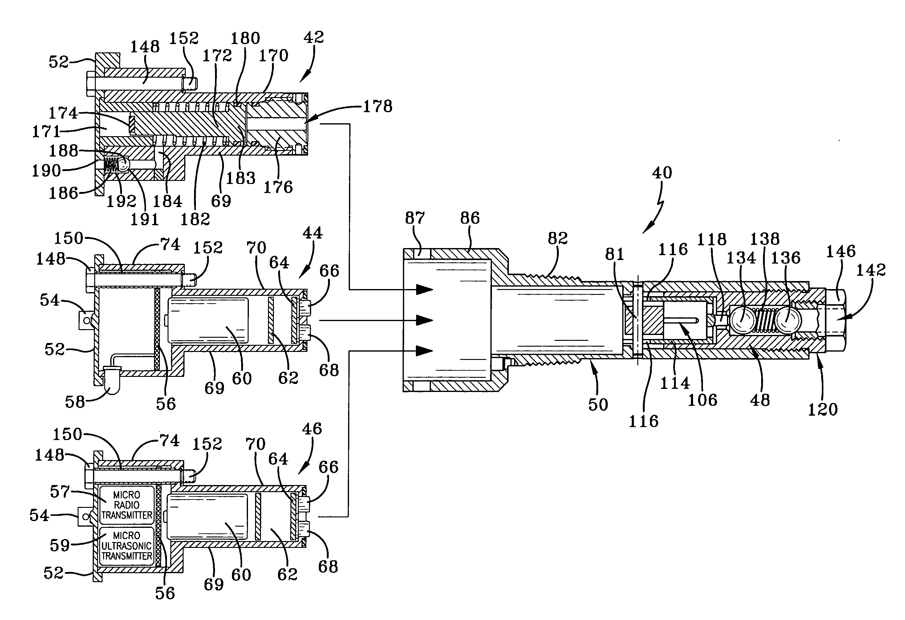
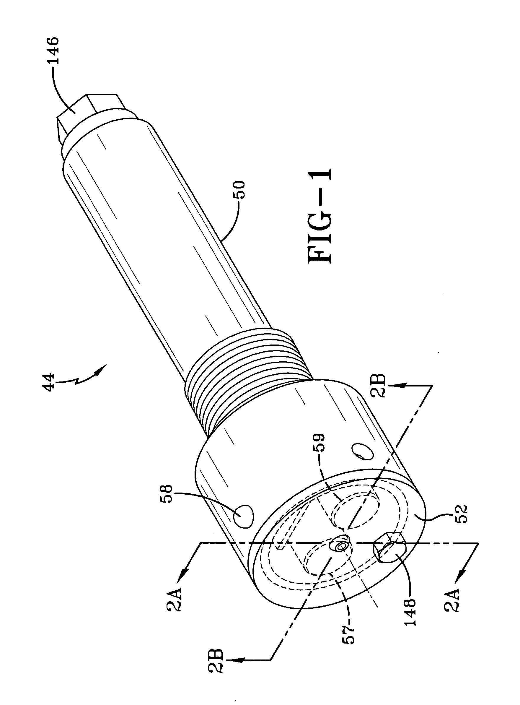
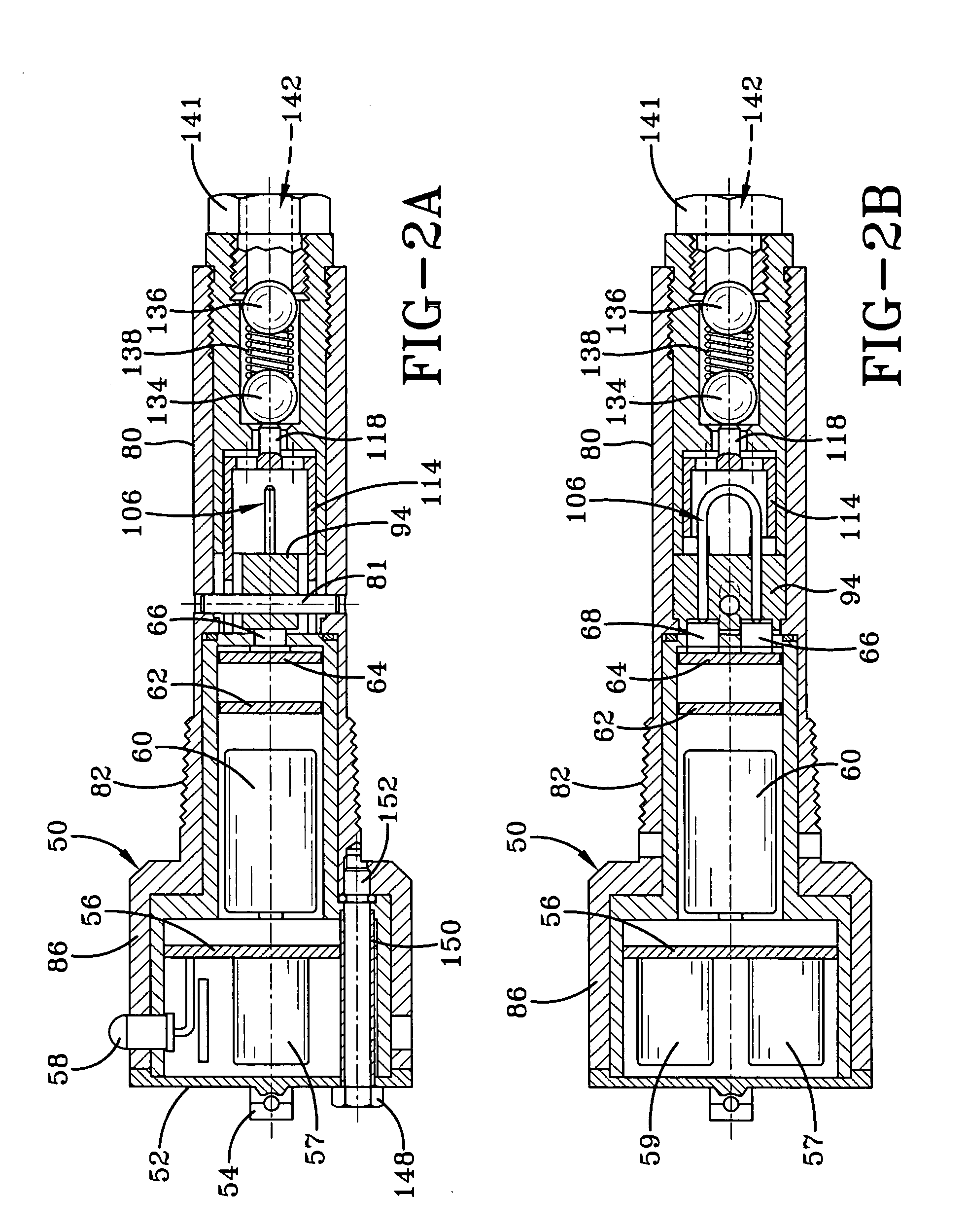
[0010]The subject invention according to one aspect provides a flexible system for detecting leaks within a double carcass hose and communicating leak detection data / status by alternative means. Alternative leak detection devices may be deployed in the system. Pursuant to one aspect of the invention, a mechanical leak detector unit with a passive ID chip; or a leak detector incorporating an LED and a passive ID chip; or a telemetry leak detector unit may be employed depending on a user's preference and application conditions. The alternative leak detector units may, pursuant to another aspect of the invention, be interchangeably deployed within a universal casing. A user may accordingly readily replace a defective leak detector unit or replace one type of leak detector with another type of leak detector unit in situ as required or desired.

Problems solved by technology

In offshore oil load and discharge operations, there is a systematic risk of oil leakage to the sea from damage to single carcass submarine or floating oil suction and discharge hoses.
Leakage from a single carcass hose may occur from a precipitous hose failure or a failure that materializes over time.
Hose failure may result from overpressure of the system, a puncture from outside, sudden tensile break of the hose body, defects in the manufacture, construction or design of the hose, etc.
In a single carcass hose construction, hose failure results in immediate oil leakage to the environment surrounding the hose.
Such leakage is highly undesirable for obvious environmental and economic reasons.
In either application, leakage from the hose results in the aforementioned undesirable consequences.
However, local conditions may make it difficult for the monitoring entity to annotate data observed.
Operational conditions may further be such (e.g. high seas) that there is substantial danger to operational personnel and also a risk that incorrect data will be observed and collected by the monitoring agent.
Existing leak monitoring systems and devices, therefore, while working well under benign conditions, may fail to provide accurate monitored data under certain other conditions.
The leak detection devices themselves may be electrically unsafe in that they have active or power components within the oil collection space, creating a fire or explosion risk.
Secondly, the communication systems in existing systems provide, at times, unreliable communication between the sensing elements and remote receivers or visual observers.
The positioning of the sensors may also be affected by the floating hose line torsion when deploying the hose line into the water.
The sensors may also be positioned incorrectly during hose line segment assembly.
Finally hose lines move as a result of seawater and weather conditions and such movement can cause sensor position change / failure, or cause erroneous data collection by the monitoring agent.
Additional deficiencies in existing art sensing systems are that they are relatively large, expensive to manufacture, cumbersome to deploy, and provide a less than satisfactory degree of reliability and flexibility.
No system affords a user the flexibility of alternatively deploying different communication devices at the preference or election of the user.

Method used


Image

  • Flexible leak detection system and method for double carcass hose
  • Flexible leak detection system and method for double carcass hose
  • Flexible leak detection system and method for double carcass hose

Examples


Embodiment Construction

[0025]Referring initially to FIG. 7, an offshore oil loading and discharge terminal is depicted by way of example incorporating a double carcass hose with built-in electronic remote oil leak detection system 10 configured pursuant to the subject invention. The offshore oil loading and discharge terminal of FIG. 7 is but one of many applications for the invention and the invention is not intended to be limited thereto. Any application in which a double carcass hose is utilized for the transportation of a fluid can utilize the subject leak detection system and the teachings herein set forth.

[0026]FIG. 7 schematically represents a tanker or platform 12. Extending from the tanker 12 is a network of submerged hose lines 14 comprising end to end connected hose segments 16 joined together by a coupling 18. Hose lines 14, while illustrated as submersible, may also be configured as floating lines if desired for an intended application. The submerged lines 14 extend to a buoy 20 and connect t...


PUM


Abstract

A fluid leak detection system mounts to a hose line segment of the type comprising at least an inner carcass and an outer containment carcass separated from the inner carcass by a collection space. The system includes a housing defined by sidewalls externally mountable to the hose line segment and having an internal housing chamber in fluid communication with the collection space. A system sensor casing mounts through a sensor housing sidewall and a plurality of alternatively configured sensor units are provided, each interchangeably coupling with the sensor casing. The sensor units detect the presence of fluid within the sensor housing and communicate the fluid status of the chamber for remote evaluation.

Description

FIELD OF THE INVENTION [0001]The invention relates generally to offshore oil load and discharge terminals and, more specifically, to hose leak detection systems deployed within the context of such oil load and discharge terminals.BACKGROUND OF THE INVENTION [0002]In offshore oil load and discharge operations, there is a systematic risk of oil leakage to the sea from damage to single carcass submarine or floating oil suction and discharge hoses. As used herein, a “single carcass hose” is a hose construction comprising only one carcass layer. Leakage from a single carcass hose may occur from a precipitous hose failure or a failure that materializes over time. Hose failure may result from overpressure of the system, a puncture from outside, sudden tensile break of the hose body, defects in the manufacture, construction or design of the hose, etc. In a single carcass hose construction, hose failure results in immediate oil leakage to the environment surrounding the hose. Such leakage is...

Claims


Application Information

Patent Timeline
Patent Type & Authority Applications(United States)
IPC IPC(8): G01M3/04
CPCG01M3/047G01M3/38G01M3/283
Inventor SPAOLONZI, MAURICIO PINTOMORENO, AIRTON DOMINGOSWERNECK, MARCELO MARTINSDE CARVALHO, CESAR COSENZA
Owner TRELLEBORG IND
Why Eureka
Try Eureka