Printing plate material, manufacturing method of the same, and plate-making method using the same

a printing plate and manufacturing method technology, applied in the field of printing plate materials, can solve the problems of substantially low printing durability, peeling of hydrophilic image receptive layer, and inability to provide printing plates having excellent printing durability and high resolution used in inkjet systems, etc., to achieve excellent printing durability, simple structure, and high resolution

Inactive Publication Date: 2008-01-17
PANASONIC CORP
View PDF6 Cites 9 Cited by
  • Summary
  • Abstract
  • Description
  • Claims
  • Application Information

AI Technical Summary

Benefits of technology

[0014]The present invention is provided to address the problems in the conventional arts. The present invention provides a printing plate material for direct plate-making on which an image forming liquid is discharged and directly attached to the printing plate material so as to form an image portion; the printing plate material achieving high resolution while having a relatively simple structure, having excellent printability and printing durability, and being used as a direct-made printing plate. The present invention further provides a manufacturing method of the printing plate material for direct plate-making and a method for making a direct-made printing plate using the printing plate material for direct plate-making.

Problems solved by technology

However, the technologies above cannot provide a printing plate having an excellent printing durability and a high resolution used for the inkjet system.
The technology disclosed in Related Art 2, for instance, has a problem where the hydrophilic image receptive layer peels off during printing when adhesion thereof to the water-resistant base is weak.
Further, the adhesion between the image forming liquid and the hydrophilic layer may be weak due to small average roughness, thus possibly leading to a substantially low printing durability.
The technology disclosed in Related Art 4 intends to improve the printing performance by optimizing the printed material originally having a water-shedding property, but does not improve a printing plate or a printing plate material provided with a hydrophilic layer having a water retention capability on a surface thereof and with a function to prevent ink spread.[Related Art 1] Japanese Patent Laid-open Publication H10-83082[Related Art 2] Japanese Patent Laid-open Publication 2001-10246[Related Art 3] Japanese Patent Laid-open Publication 2003-231374[Related Art 4] Japanese Patent Laid-open Publication H10-235989
As described above, the conventional printing plate materials and the plate-making methods using the same have the problems where it is difficult to provide a printing plate having printability represented as printing durability and dampening water retainability, and, at the same time, achieving a high-resolution image portion.

Method used


Image

  • Printing plate material, manufacturing method of the same, and plate-making method using the same
  • Printing plate material, manufacturing method of the same, and plate-making method using the same
  • Printing plate material, manufacturing method of the same, and plate-making method using the same

Examples


embodiment example 1

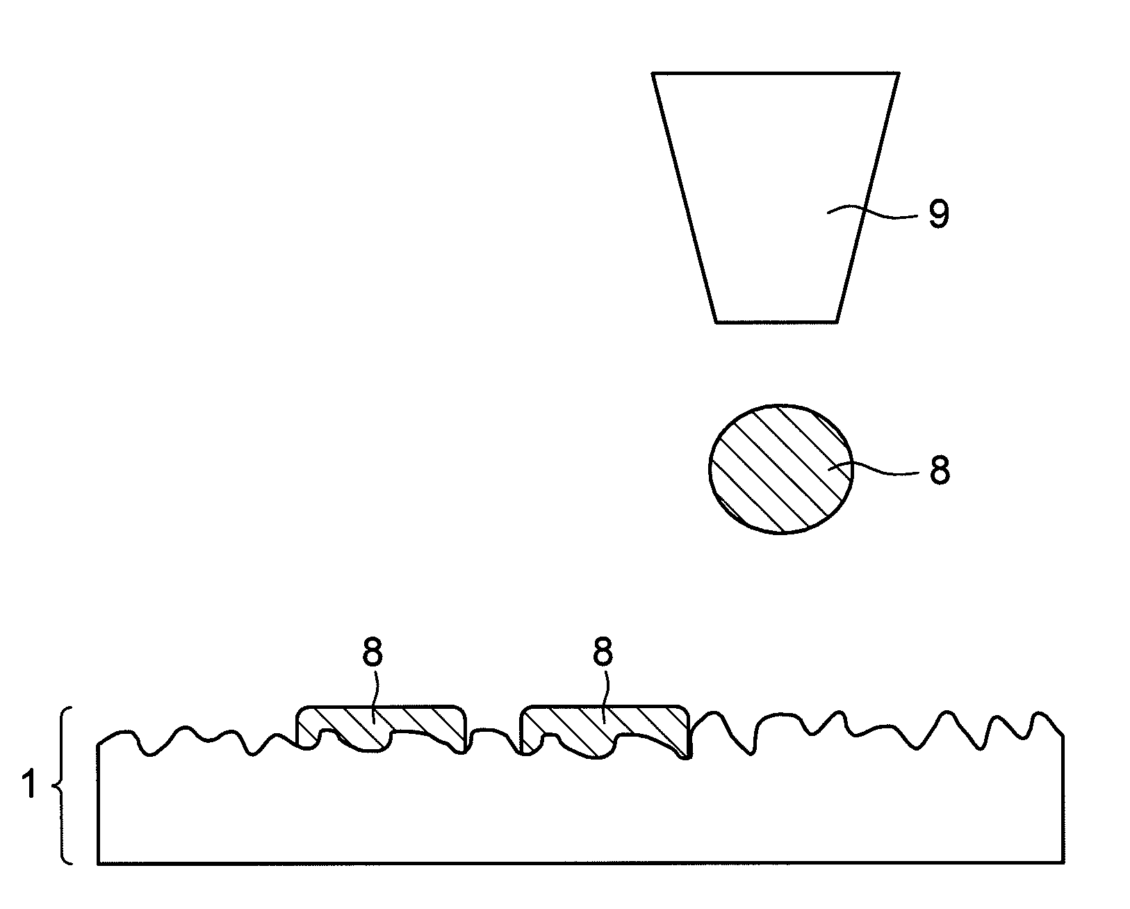
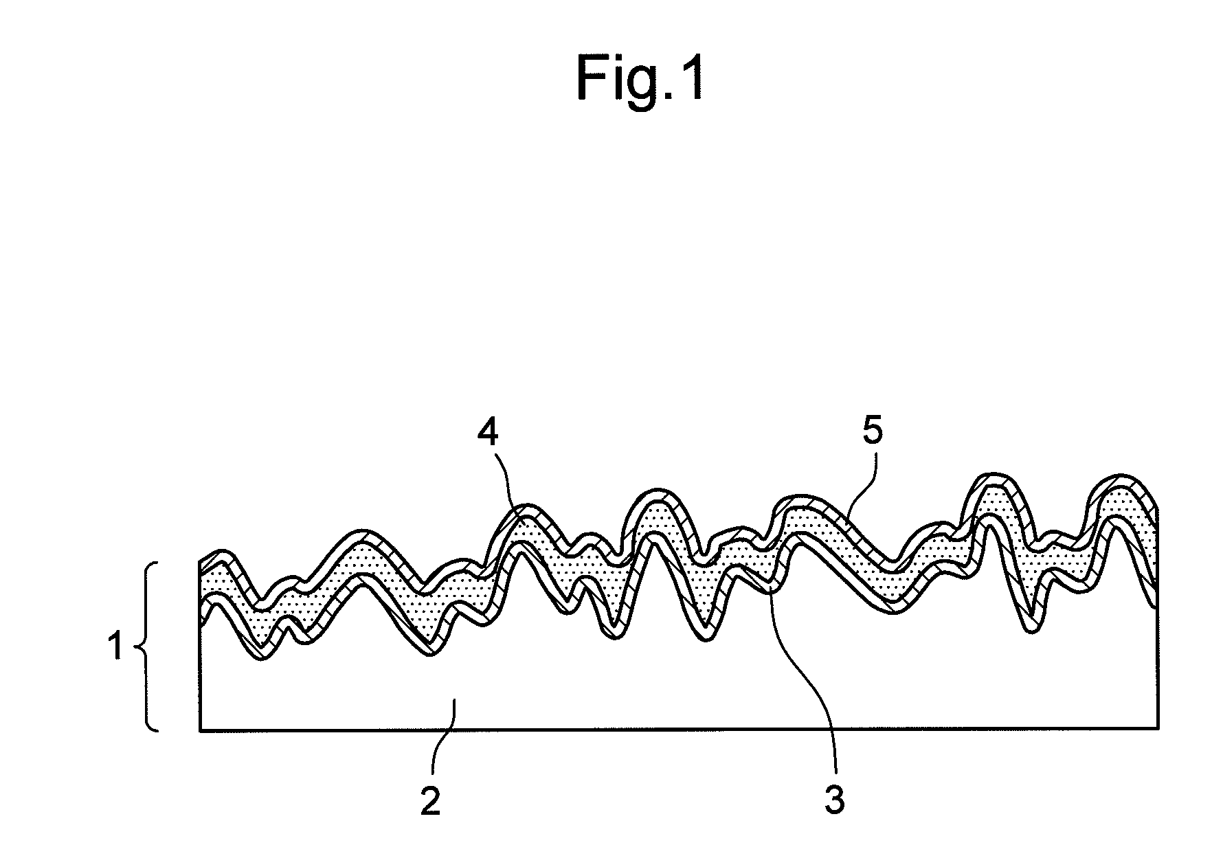
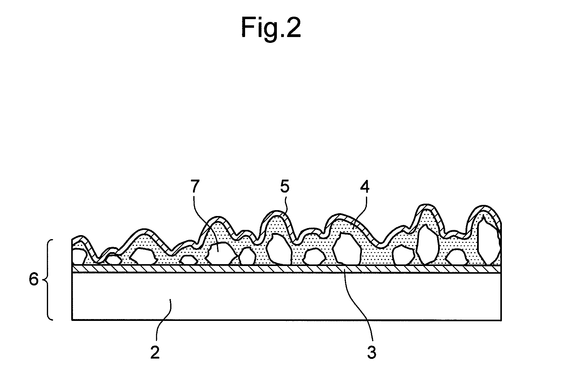
[0130]A primer manufactured by Matsushita Electric Works, Ltd. is applied to and dried on the surface of flat PET film base material 2, so as to provide a protective layer. A product of Matsushita Electric Works, Ltd., “Frescera-P,” is applied to and dried on the protective layer, so as to provide photocatalytic hydrophilic layer 4. Then, photocatalytic hydrophilic layer 4 is exposed to an ultraviolet light including a wavelength of 350 nm to 400 nm for 3 minutes for hydrophilization, so as to hydrophilize the layer. Subsequently, PET film base material 2 is dipped in and removed from a water solution of a fluorosurfactant (“Surfron” manufactured by Seimi Chemical Co., Ltd.), whose concentration is conditioned at a predetermined level. PET film base material 2 is then dried so as to provide dot control layer 5; and printing plate material for direct plate-making 1 is obtained.

[0131]Onto the surface of obtained printing plate material 1, 0.5 cc of ultraviolet hardening resin 8 (a sur...

embodiment example 2

[0133]A product of Matsushita Electric Works, Ltd., “Frescera-P,” is applied to and dried on the surface of flat PET film base material 2, so as to provide photocatalytic hydrophilic layer 4. Subsequently, PET film base material 2 is dipped in and removed from a water solution of a fluorosurfactant (“Surfron” manufactured by Seimi Chemical Co., Ltd.) having 0.3% by weight. PET film base material 2 is then dried so as to provide dot control layer 5; and printing plate material for direct plate-making 1 is obtained.

[0134]Onto the surface of obtained printing plate material 1, 1.0 cc of ultraviolet hardening resin 8 is applied from a pipette, and then spread of the droplet is observed in 5 seconds. Table 2 below shows the results.

embodiment example 3

[0137]Hydrophilic layer 4 and dot control layer 5 are provided on PET film base material 2 having a variety of surface roughness, in the method described in the Embodiment Example 1. Thereby, printing plate material for direct plate-making 1 is obtained.

[0138]Ultraviolet hardening resin 8 is discharged from the inkjet recording head in a form of a 3-pl droplet to obtained printing plate material 1, in the method described in Embodiment Example 2. Then, ultraviolet having a wavelength of 350 nm to 400 nm is irradiated for 4 seconds, so as to harden the droplet; and then a direct-made printing plate provided with a formed image is obtained. An assessment of the dot adhesion and a dot shape of the printing plate is shown in Table 3.

TABLE 3RyRaDot size(μm)(μm)PeelingDot shape(μm)Embodiment3.170.3LargeFair (protrusion)25–30Example 36.090.58MediumFair (protrusion)20–258.711.03MediumFair (protrusion)20–259.241.21NegligibleGood20–259.891.31NegligibleGood20–2514.171.88Most negligiblePoor (sh...


PUM


Abstract

A printing plate material for direct plate-making includes a PET film base material; a protective layer and a photocatalytic hydrophilic layer provided on the base material; and a dot control layer provided on the hydrophilic layer and having a critical surface tension equal to or lower than a surface tension of an image forming liquid. The image forming liquid is discharged from an inkjet recording head onto a surface of the printing plate material for direct plate-making and is hardened. Thereby, a direct-made printing plate is obtained.

Description

BACKGROUND OF THE INVENTION[0001]1. Field of the Invention[0002]The present invention relates to a printing plate material for direct plate-making, a manufacturing method of the same, and a method for making a direct-made printing plate using the same, the direct-made printing plate being made of the printing plate material for direct plate-making, on which an image forming liquid is selectively discharged according to a predetermined image pattern, and thereby an image portion is formed.[0003]2. Description of Related Art[0004]Conventional planographic printing employs an aluminum-based PS plate provided with a photosensitive resin layer (an image forming layer) evenly coated on a surface thereof. Making a printing plate using such a PS plate generally includes a number of processes, including an image forming process, a developing process, a washing process, a gumming process, a drying process, and the like (e.g., Related Art 1). In the image forming process, the PS plate is expos...

Claims


Application Information

Patent Timeline
Patent Type & Authority Applications(United States)
IPC IPC(8): B41C3/08
CPCB41C1/1066B41N1/086B41N1/08B41M2205/12
Inventor OHIGASHI, CHIAKIIEMURA, SHIGERU
Owner PANASONIC CORP
Why Eureka
Try Eureka