Switching electromagnetic moving system

a technology of electromagnetic moving system and switching electromagnetic field, which is applied in the direction of power supply line details, transportation and packaging, toys, etc., can solve the problems of difficult to generate reliable high speed motion of such vehicles, object made to travel at high speed can lose stability and move from the track, and require much more power to achieve motion. , to achieve the effect of more power economy

Inactive Publication Date: 2008-01-17
INDAL DESIGN LAB
View PDF22 Cites 31 Cited by
  • Summary
  • Abstract
  • Description
  • Claims
  • Application Information

AI Technical Summary

Benefits of technology

[0018]There are two options in respect to the sensors number. According to the first option, each track section has one sensor that is a Hall effect sensor, and it controls switches in preceding and subsequent track sections. According to the second option, for more power economy, each track section has two sensors that are Hall effect sens...

Problems solved by technology

The main problem of all such known systems is that it is difficult to generate reliable high speed motion of such vehicles because of the absence of attraction between the vehicle and the track, especially at higher speed on turns, and also when the track follows a vertical or nearly vertical path as in a vertical ring or spiral.
Even when track sections are configured horizontally an object made to travel at high speed can lose stability and...

Method used


Image

  • Switching electromagnetic moving system
  • Switching electromagnetic moving system
  • Switching electromagnetic moving system

Examples


Embodiment Construction

[0032]The present invention will be described in detail below with reference to the accompanying drawings.

[0033]FIGS. 1-6A show embodiments of the present invention.

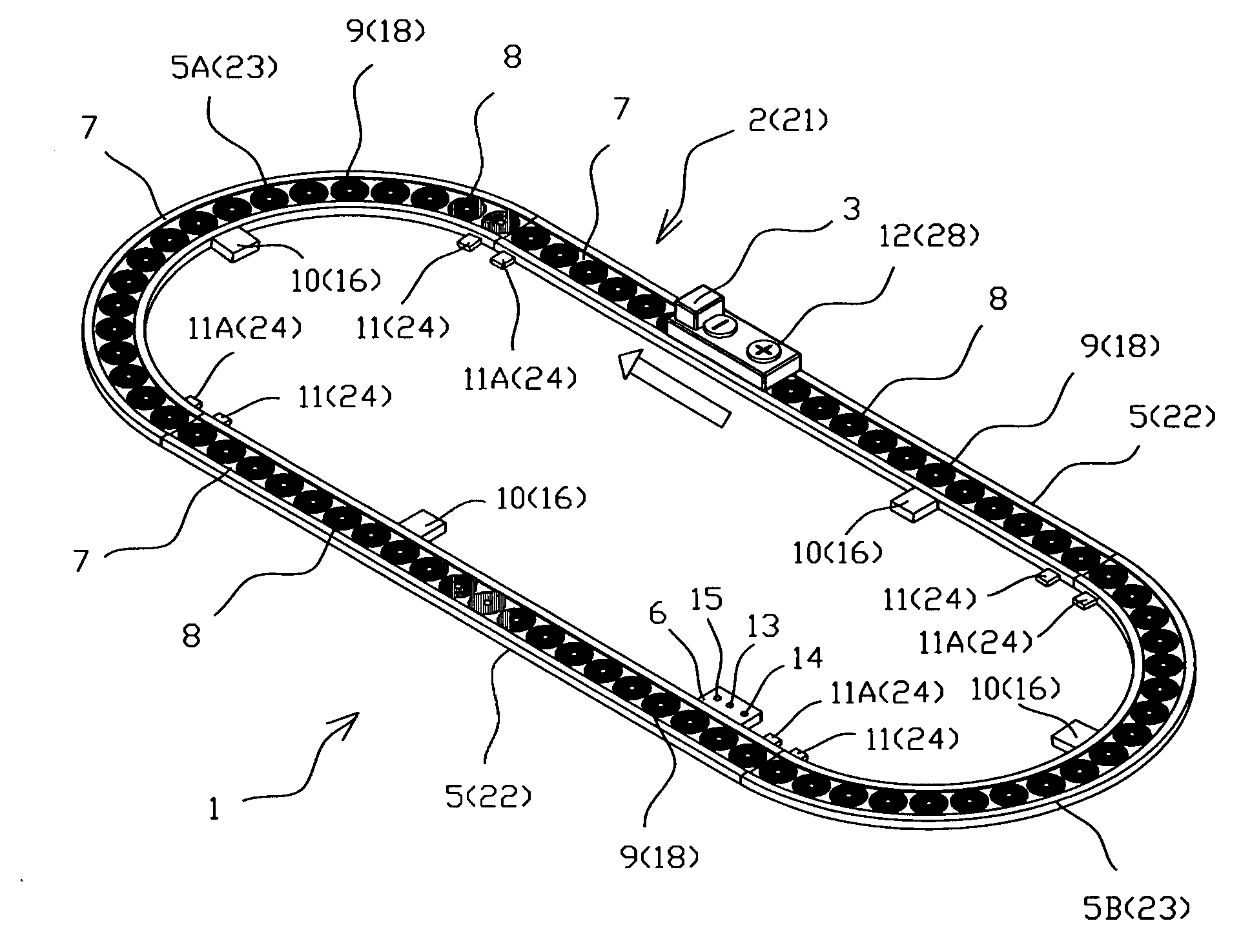
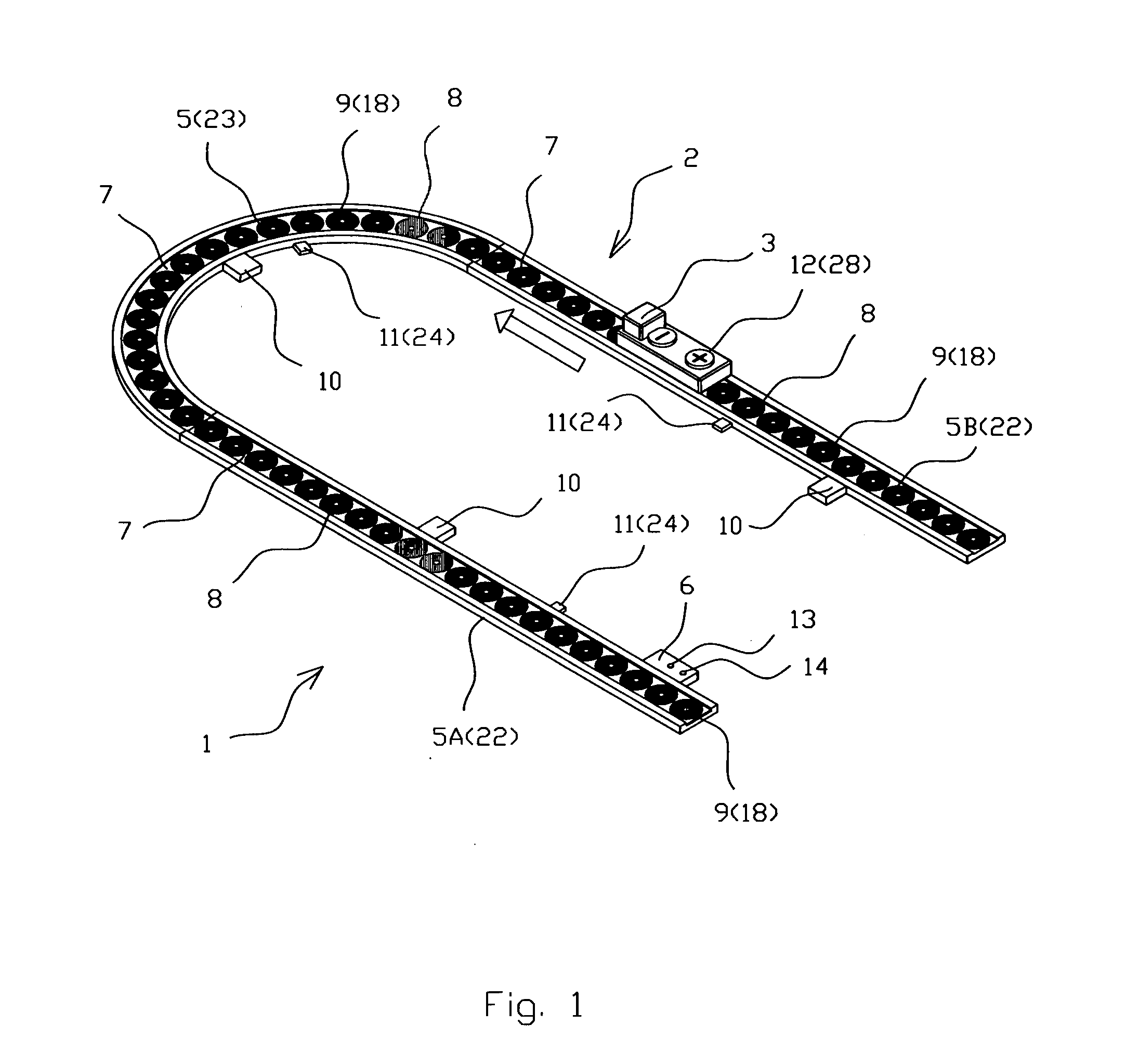
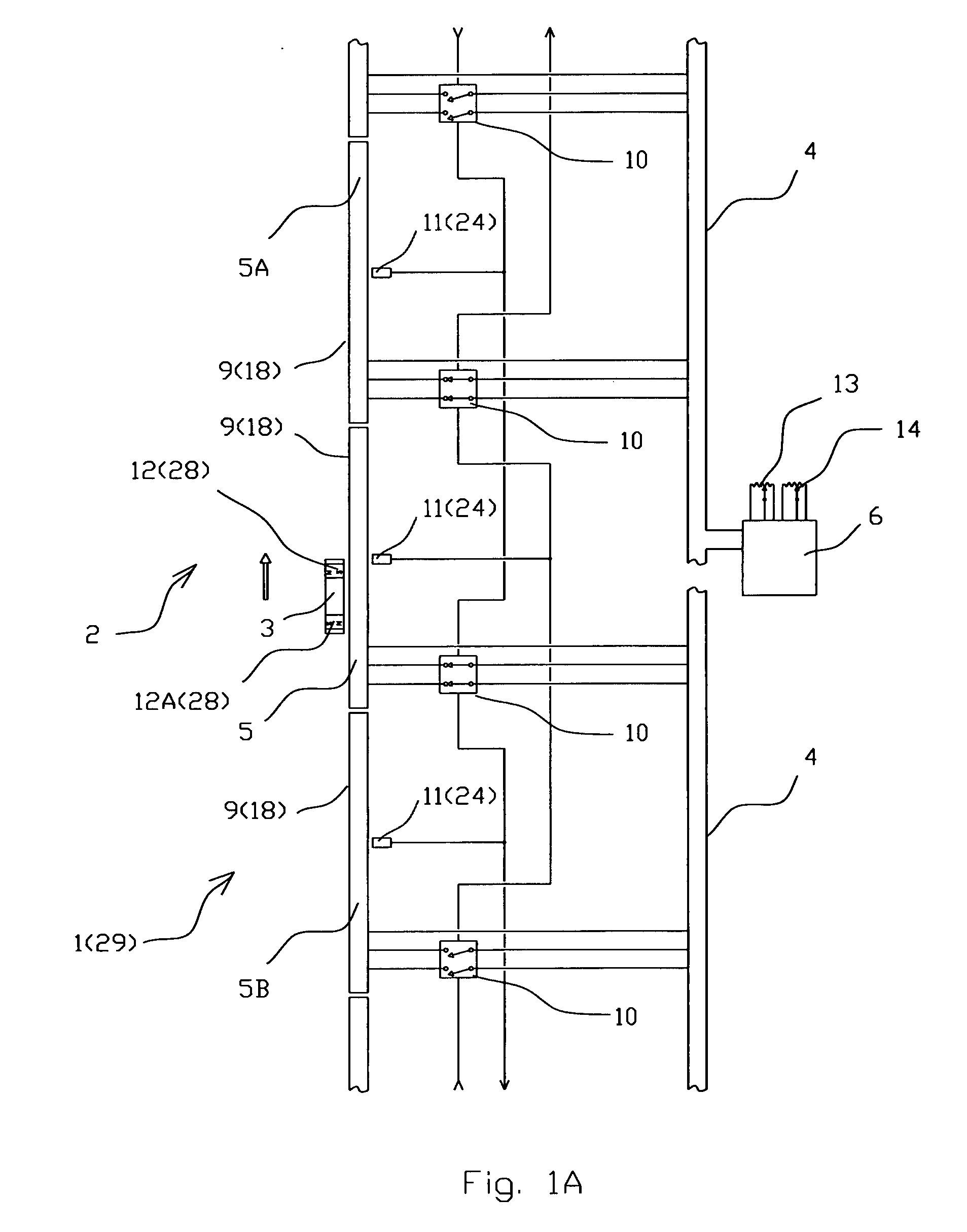
[0034]The switching electromagnetic moving system 1 according to the preferred embodiment (FIGS. 1, 1A, 2A and 2B), is comprised of one track 2 and one moving body 3 located on the track 2. The track 2 is comprised of a power buss 4, three track sections 5 and a controller 6. Each of the track sections 5 has a contact surface 7 and is comprised of electrically connected coil windings 8 spaced apart in a series way along the track section 5 and forms a multi-phase linear stator 9. The stator 9 is executed as 3 phase linear stator 9. The track sections 5 are electrically connected in parallel with the power buss 4. Each coil winding 8 is located at a plane substantially coincides with the contact surface 7 and has a magnetic axis substantially perpendicular to the contact surface 7. Each track section 5 has a switch 10 and...


PUM


Abstract

A switching electromagnetic moving system is comprised of at least one track and at least one moving body located on the track. The track is comprised of a power buss, at least two track sections and a controller. Each track section has a contact surface and comprises electrically connected coil windings spaced apart in a series way to form a multi-phase linear stator. Each track section has a switch and at least one sensor to detect the position of the moving body on the track. For each track section the sensor of the preceding track section relative to the direction of travel of the moving body controls the switch to power on and the sensor of the subsequent track section controls the switch to power off.

Description

FIELD OF THE INVENTION[0001]The present invention relates generally to electromagnetic systems for moving mechanical bodies along predefined paths. More particularly, the present invention relates to toy and / or entertainment systems, and all subsystems in which it is useful to controllably move an object upon a surface. The present invention is particularly, but not exclusively, useful for systems that relate to toy motion devices such as vehicles.BACKGROUND OF THE INVENTION[0002]There are numerous designs of electromagnetic motion control systems executed as miniature toy railways that include a track and at least one vehicle located on said track.[0003]There are known systems of this type, for example, U.S. Pat. No 4,861,306 “Toy Cog Railway” and U.S. Pat. No. 6,648,724 “Toy Railway Liquid Transfer Facility”, that include the track (platform, chassis) driven by an engine and vehicle mounted on said track.[0004]Another type of system, for example, U.S. Pat. No. 3,729,866 “Toy Railw...

Claims


Application Information

Patent Timeline
IPC IPC(8): B60L13/03B60L13/06
CPCA63H19/24A63H2018/165B60L2200/26B60M1/10B60L13/03
Inventor LOPATINSKY, EDWARDFEDOSEYEV, LEVSCHAEFER, DANIEL
Owner INDAL DESIGN LAB
Why Eureka
Try Eureka