
Inline swivel connection for multi-lumen tubing

Active Publication Date: 2008-01-17
KCI LICENSING INC
View PDF26 Cites 51 Cited by
  • Summary
  • Abstract
  • Description
  • Claims
  • Application Information

AI Technical Summary

Benefits of technology

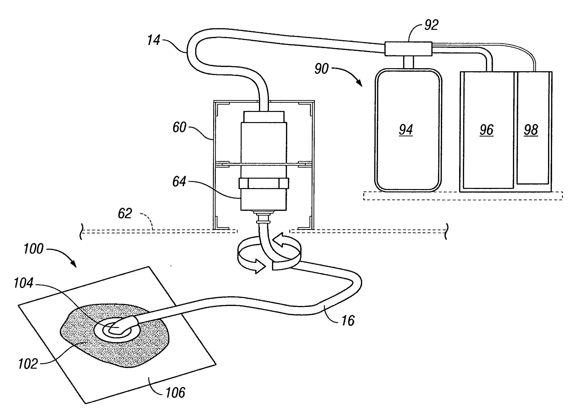
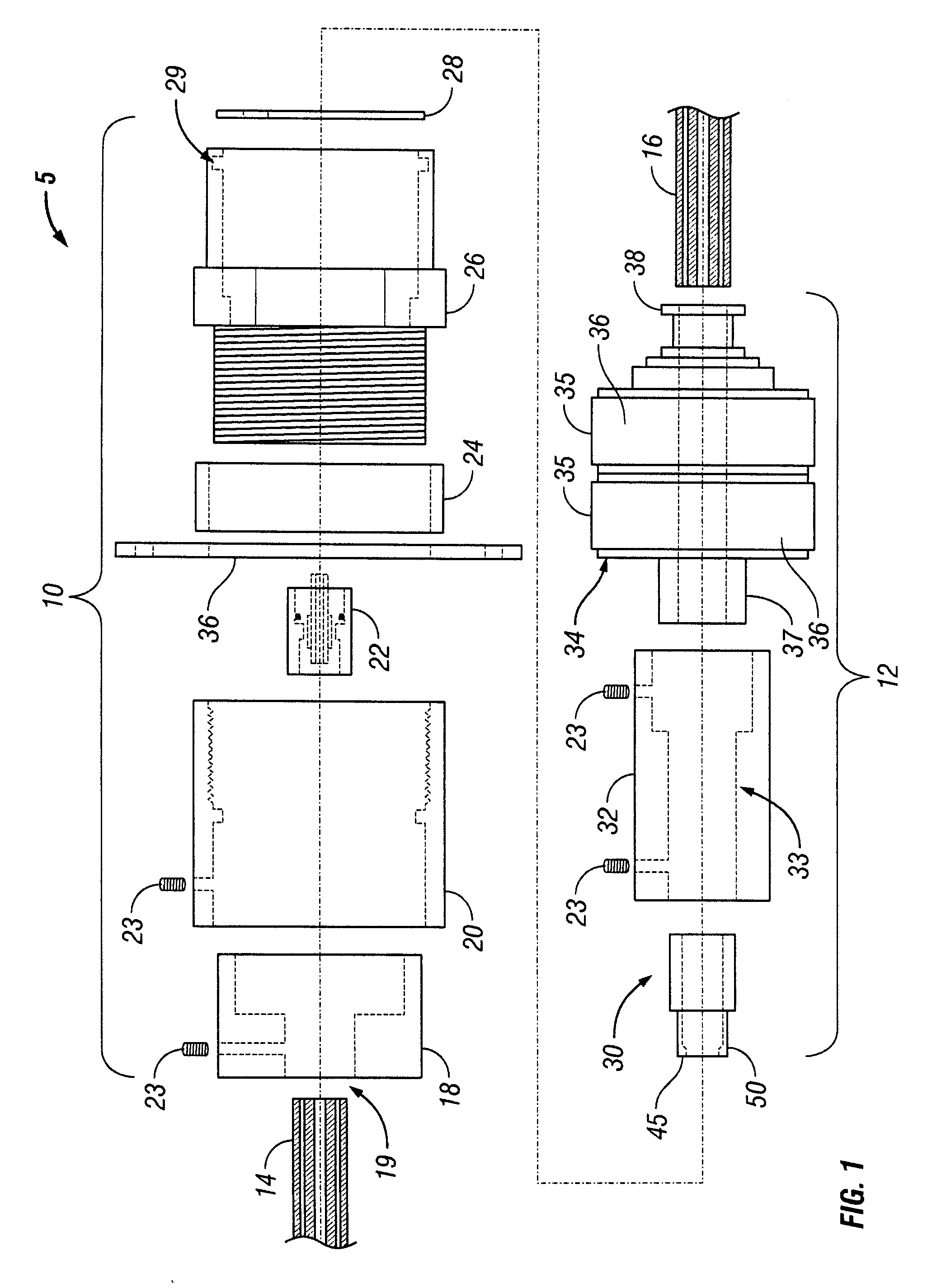
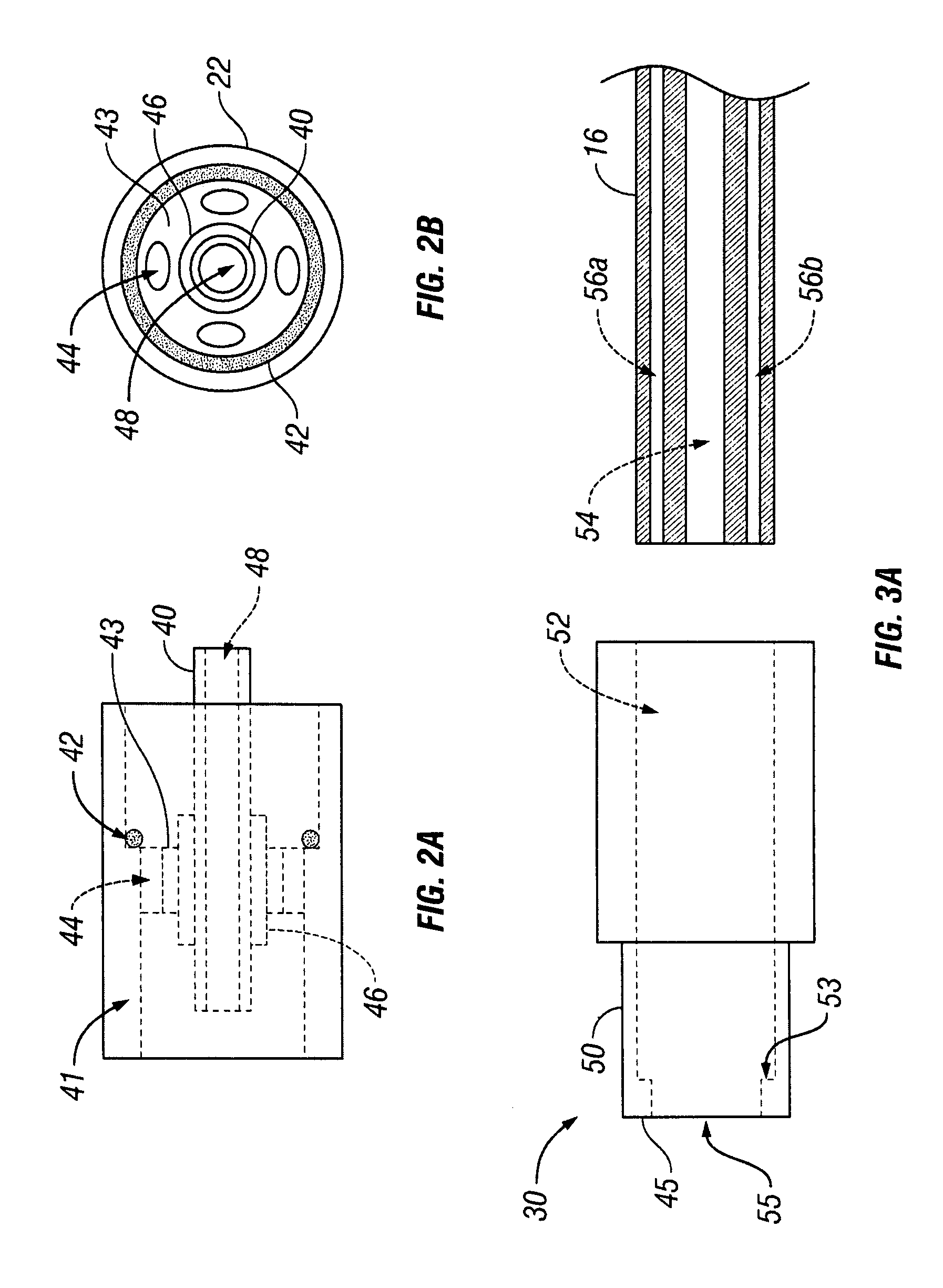
[0019] In accordance with one embodiment of the present invention, an apparatus for connecting multi-lumen conduits is provided. In such an embodiment, the apparatus comprises a conduit adapter and a conduit collar. The conduit adapter may include a housing, a bayonet connector, and a support member connecting the housing and the bayonet connector. The bayonet connector generally has a single bore extending lengthwise through the connector, and optionally a conduit stop that limits the extent to which the connector may be inserted into a conduit. The support member includes at least one aperture that permits fluid or gas communication through the support member. The conduit collar has a first end and a second end. The first end is sized for insertion into the housing, and the second end is adapted to receive a first multi-lumen conduit. The housing is adapted to receive the first end of the conduit collar such that the bayonet connector engages a primary lumen of the first multi-lumen conduit and the primary lumen of the first multi-lumen conduit fluidly communicates with the bore. The housing also is adapted to receive a second multi-lumen conduit such that the bayonet connector engages a primary lumen of the second multi-lumen conduit, and the primary lumen of the second multi-lumen conduit fluidly communicates with the bore and the primary lumen of the first multi-lumen conduit. The conduit adapter and the conduit collar are capable of 360 degree rotation relative to each other about an axis shared by the conduit adapter and the conduit collar, while permitting fluid communication between ancillary lumens of the first multi-lumen conduit and the second multi-lumen conduit through the aperture in the support member.

Problems solved by technology

Unfortunately, this process is hampered when a wound is large or has become infected.
Without sufficient blood flow, the epithelial and subcutaneous tissues surrounding the wound not only receive diminished oxygen and nutrients, but are also less able to successfully fight bacterial infection and, thus, less able to naturally close the wound and heal the tissue.
Additionally, some wounds harden and inflame to such a degree that closure by stapling or suturing is not feasible.
With human patients, it is often possible (although certainly not always possible) to insist upon reduced mobility or even immobile conditions in order to carry out the tissue treatment.
With animal patients, this is of course generally not possible at all unless the animal is sedated.
As the preference is to permit the tissue to heal over a period of time, it is generally not practical to maintain sedation of an animal to carry out either research or treatment with reduced pressure application.
The problems that arise therefore in maintaining an effective connection between the negative pressure instrumentation and the reduced pressure treatment dressing can become complex.
A direct connection between the instrumentation and the wound dressing can quickly become disabled with the movement of the subject animal even within a relatively small enclosure.
However, where multi-lumen tubing is utilized, maintaining the structural simplicity of the connector becomes more challenging.
Such efforts clearly suffer, however, from the complexities associated with maintaining a turntable integrating all of the electronic and electrical components necessary to carry out the reduced pressure treatment regimens prescribed.
In addition, such systems generally work only for very large animal subjects as even with the best support structures a greater force is required to initiate the rotation of the entire instrument laden turntable.
A number of problems arise in attempting to provide a swivel connector for a multi-lumen tube of the structure described above.
An added concern, however, is the increased risk of cross-contamination between the larger primary lumen and the ancillary smaller lumens that need to remain clear.
Any leakage in the swivel connector structure could cause fluids and solids to find their way into the small ancillary lumens, thereby clogging those lines and reducing or preventing the effectiveness of the reduced pressure treatment system.
One further complication that arises as a result of the application of such reduced pressure treatment systems to veterinary environments is the wide range in animal size that the systems must accommodate.
Providing a tight seal, however, works contrary to the general requirement of providing an easily rotatable connection.
Smaller animals and small children may be wholly unable to rotate a tight connection, resulting in an ineffective swivel connector.

Method used


Image

  • Inline swivel connection for multi-lumen tubing
  • Inline swivel connection for multi-lumen tubing
  • Inline swivel connection for multi-lumen tubing

Examples


Embodiment Construction

[0033] In the following detailed description of preferred embodiments, reference is made to the accompanying drawings which form a part hereof, and in which is shown by way of illustration specific preferred embodiments in which the invention may be practiced. These embodiments are described in sufficient detail to enable those skilled in the art to practice the invention, and it is understood that other embodiments may be utilized and that logical mechanical, structural, and chemical changes may be made without departing from the spirit or scope of the invention. To avoid detail not necessary to enable those skilled in the art to practice the invention, the description may omit certain information known to those skilled in the art. The following detailed description is, therefore, not to be taken in a limiting sense, and the scope of the present invention is defined only by the appended claims.

[0034] A rotating swivel connector according to one embodiment of the present invention ...


PUM


Abstract

An apparatus for connecting multi-lumen conduits is described. The apparatus may include a conduit adapter and a conduit collar. The conduit adapter may include a housing, a bayonet connector, and a support member connecting the housing and the bayonet connector. The support member has an aperture that permits fluid communication through the support member. One end of the conduit collar is sized for insertion into the housing, and a second end is adapted to receive a first multi-lumen conduit. The housing also is adapted to receive a second multi-lumen conduit. The bayonet connector engages a primary lumen of the first multi-lumen conduit and the second multi-lumen conduit such that the primary lumen of the second multi-lumen conduit fluidly communicates with the primary lumen of the first multi-lumen conduit. The conduit adapter and the conduit collar are capable of 360 degree rotation relative to each other about a common axis.

Description

CROSS-REFERENCE TO RELATED APPLICATIONS [0001] This application claims the benefit of and priority to U.S. Provisional Application No. 60 / 794,724 filed Apr. 25, 2006, which is hereby incorporated by reference.BACKGROUND OF THE INVENTION [0002] 1. Field of the Invention [0003] The invention relates generally to methods and devices for conducting fluids and gases within a reduced pressure treatment system The invention relates more specifically to an inline connector for multi-lumen tubing that allows free rotation of one end of the tubing with respect to the other end of the tubing. [0004] 2. Description of Related Art [0005] General Background of Tissue Treatment [0006] Various therapies have been developed over time to facilitate the process of tissue growth and healing. Wound closure is one application of tissue growth and healing. Wound closure generally involves the inward migration of epithelial and subcutaneous tissue adjacent the wound. This migration is ordinarily assisted b...

Claims


Application Information

Patent Timeline
IPC IPC(8): A61M1/00A61M39/10
CPCA61M1/0088A61M2039/1077A61M39/1055A61M39/105Y10S285/904Y10T137/85978A61M1/86A61M1/90A61M1/912
Inventor SINGH, VINAY K.SWAIN, LARRY D.CORNET, DOUGLAS A.WILKES, ROBERT P.HEATON, KEITH PATRICKLOCKE, CHRISTOPHER BRIANROBINSON, TIMOTHY MARK
Owner KCI LICENSING INC
Learn More