Eureka AIR delivers breakthrough ideas for toughest innovation challenges, trusted by R&D personnel around the world.

Cemented tungsten carbide rock bit cone

Inactive Publication Date: 2008-01-17
BAKER HUGHES INC
View PDF13 Cites 80 Cited by
  • Summary
  • Abstract
  • Description
  • Claims
  • Application Information

AI Technical Summary

Benefits of technology

[0042]The invention has significant advantages. The cone is very resistant to erosion and wear as it is formed of a material much harder than the prior art steel. Labor intensive hardfacing applications are reduced or eliminated.

Problems solved by technology

In drilling applications involving extended periods of operation, or a high content of abrasive particles in the formation and drilling fluid, extensive erosion and abrasion of the cone may occur, causing a loss of inserts.
Hardfacing applications are labor intensive, not well controlled or repeatable and also may inhibit the cutting structure because of the inherent bluntness of the resulting hardfaced teeth.
However, sharpening the hardfaced teeth by grinding adds another relatively difficult and expensive step in the manufacturing process.
Also, the portions of the cone shell that are not hardfaced may erode extensively in abrasive drilling conditions, causing a loss of teeth or the entire cone.
Since the particle-matrix bit crown cannot be readily machined because of its hardness after the casting process, the cavity of the mold must be formed with the net desired shape and size for the bit.
The mold is intricate and requires extensive machining and hand finishing.
The mold must usually be broken subsequent to the infiltration cycle to remove the finished bit crown and used only once, making particle-matrix bits costly.
The temperature for sintering a tungsten carbide cutting element is about 1320-1370 degrees C. High temperature processing in an oxygen containing atmosphere at these temperatures is not possible because of the oxidation that would occur to these materials at the processing temperature.
The sintering step in cemented carbide results in significant shrinkage because the porosity in the pressed particulate component is eliminated as the binder material melts and the resulting surface tension of the molten binder pulls the particles together.

Method used


Image

  • Cemented tungsten carbide rock bit cone
  • Cemented tungsten carbide rock bit cone
  • Cemented tungsten carbide rock bit cone

Examples


Embodiment Construction

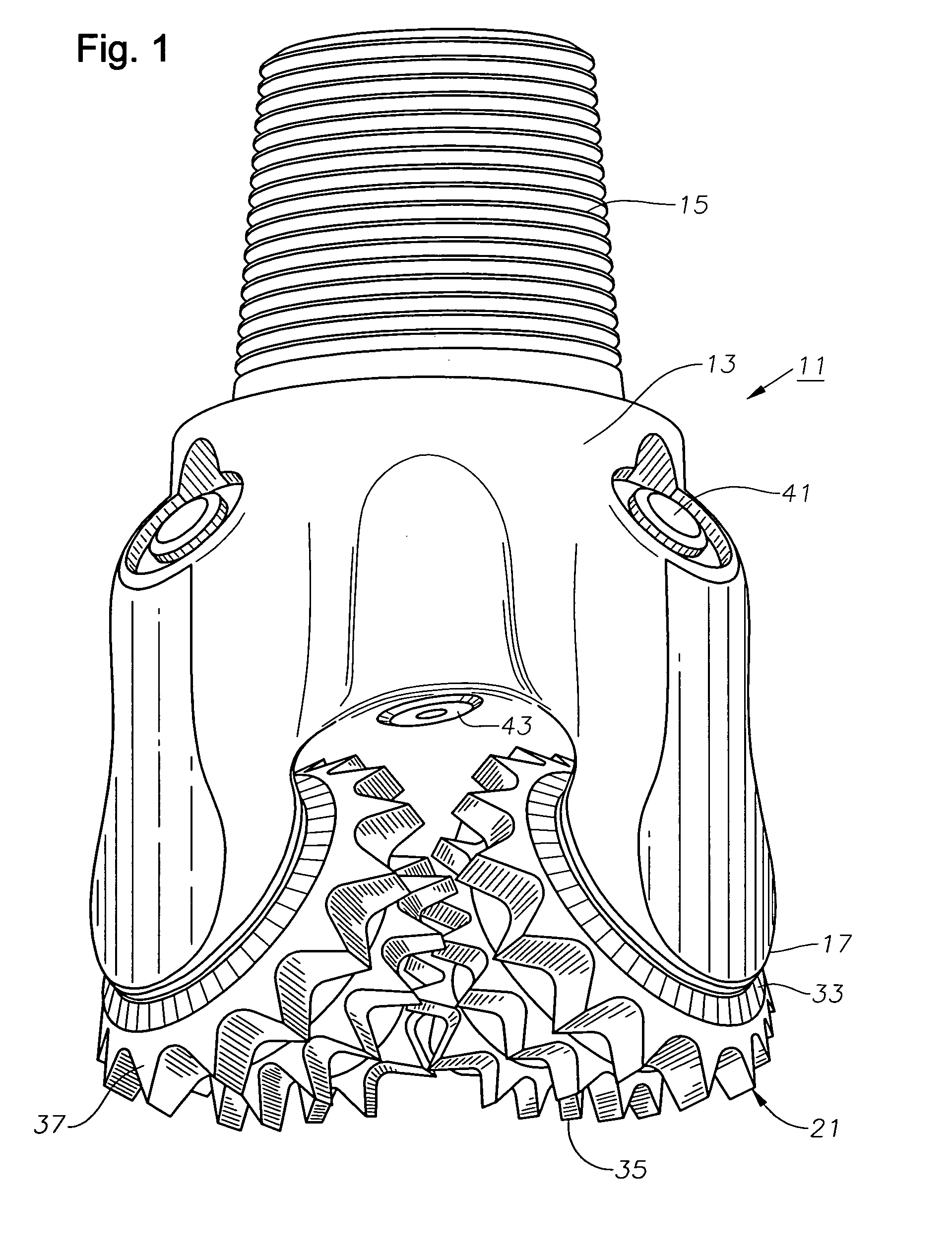
[0021]Referring to FIG. 1, earth-boring bit 11 has a body 13 with threads 15 formed on its upper end for connection into a drill string. Body 13 has three integrally formed bit legs 17. Each bit leg 17 has a bearing pin 19, as illustrated in FIG. 2. Preferably, bit body 13 and bearing pins 19 are formed conventionally of a steel alloy.

[0022]Each bit leg 17 supports a cone 21 on its bearing pin 19 (FIG. 2). Each cone 21 has a cavity 23 that is cylindrical for forming a journal bearing surface with bearing pin 19. Cavity 23 also has a flat thrust shoulder 24 for absorbing thrust imposed by the drill string on cone 21. Each cone 21 has a lock groove 25 formed in its cavity 23. In the example shown, a snap ring 27 is located in groove 25 and a mating groove formed on bearing pin 19 for locking cone 21 to bearing pin 19. Cone 21 has a seal groove 29 for receiving a seal 31. Seal groove 29 is located adjacent a back face 33 of cone 21. Seal 31 is shown to be an elastomeric ring, but it co...


PUM


Abstract

An earth-boring bit has a steel body and bearing pin for rotatably supporting a cone. The cone has an exterior surface containing rows of cutting elements. The cone and cutting elements are formed of cemented tungsten carbide. The cone may be manufactured by applying pressure to a mixture of hard particles and metal alloy powder to form a billet, then machining the billet to a desired over-sized conical shaped product. Then the conical-shaped product is liquid-phase sintered to a desired density, which causes shrinking to the desired final shape.

Description

FIELD OF THE INVENTION[0001]This invention relates in general to earth-boring bits having rotatable cones, and in particular to an earth boring bit having cones formed of a sintered particle composite material such as cemented tungsten carbide.BACKGROUND OF THE INVENTION[0002]Rotary drill bits are commonly used for drilling bore holes or wells in earth formations. One type of rotary drill bit is the roller cone bit (often referred to as a “rock” bit), which typically includes a plurality of conical cutting elements secured to legs dependent from the bit body. All bits have a body with a threaded upper end for connection to a drill string. The body has three depending legs each having a bearing pin. A rotatable cone is mounted on each of the bearing pins.[0003]One type of bit has cones that have cemented carbide inserts or compacts press-fitted into mating holes formed in the exterior of the cone. The inserts protrude past the shell for engaging and disintegrating the earth formation...

Claims


Application Information

Patent Timeline
IPC IPC(8): E21B10/36B21K5/04
CPCE21B10/50E21B10/46
Inventor SMITH, REDD H.BURGESS, TREVOREASON, JIMMY W.
Owner BAKER HUGHES INC
Why Eureka
Eureka Blog
Learn More