Lock-Up Device Of Hydraulic Torque Transmitting Apparatus

a transmission apparatus and lock-up device technology, which is applied in the direction of rotary clutches, fluid couplings, gearings, etc., can solve the problems of deterioration of operating responsivity in the lock-up device, poor lock-up operation responsivity, and too much time to lower, so as to improve the lock-up operation responsivity during coasting

Inactive Publication Date: 2008-01-17
EXEDY CORP
View PDF4 Cites 4 Cited by
  • Summary
  • Abstract
  • Description
  • Claims
  • Application Information

AI Technical Summary

Benefits of technology

[0031] In this lock-up device according to the present invention, the

Problems solved by technology

However, if the lock-up operation range is widened to a coasting range (in a state that the output rotation speed is higher than the input rotation speed), the problem of deterioration of operating responsivity in the lock-up device becomes remarkable.
Conseq

Method used


Image

  • Lock-Up Device Of Hydraulic Torque Transmitting Apparatus
  • Lock-Up Device Of Hydraulic Torque Transmitting Apparatus
  • Lock-Up Device Of Hydraulic Torque Transmitting Apparatus

Examples


experiment 1

(Experiment 1)

[0069] The lock-up ON responsivities were compared between the conventional lock-up device and the lock-up device according to the present invention. The measurement was carried out using the same products except for the lock-up device, i.e., the lock-up piston and the damper.

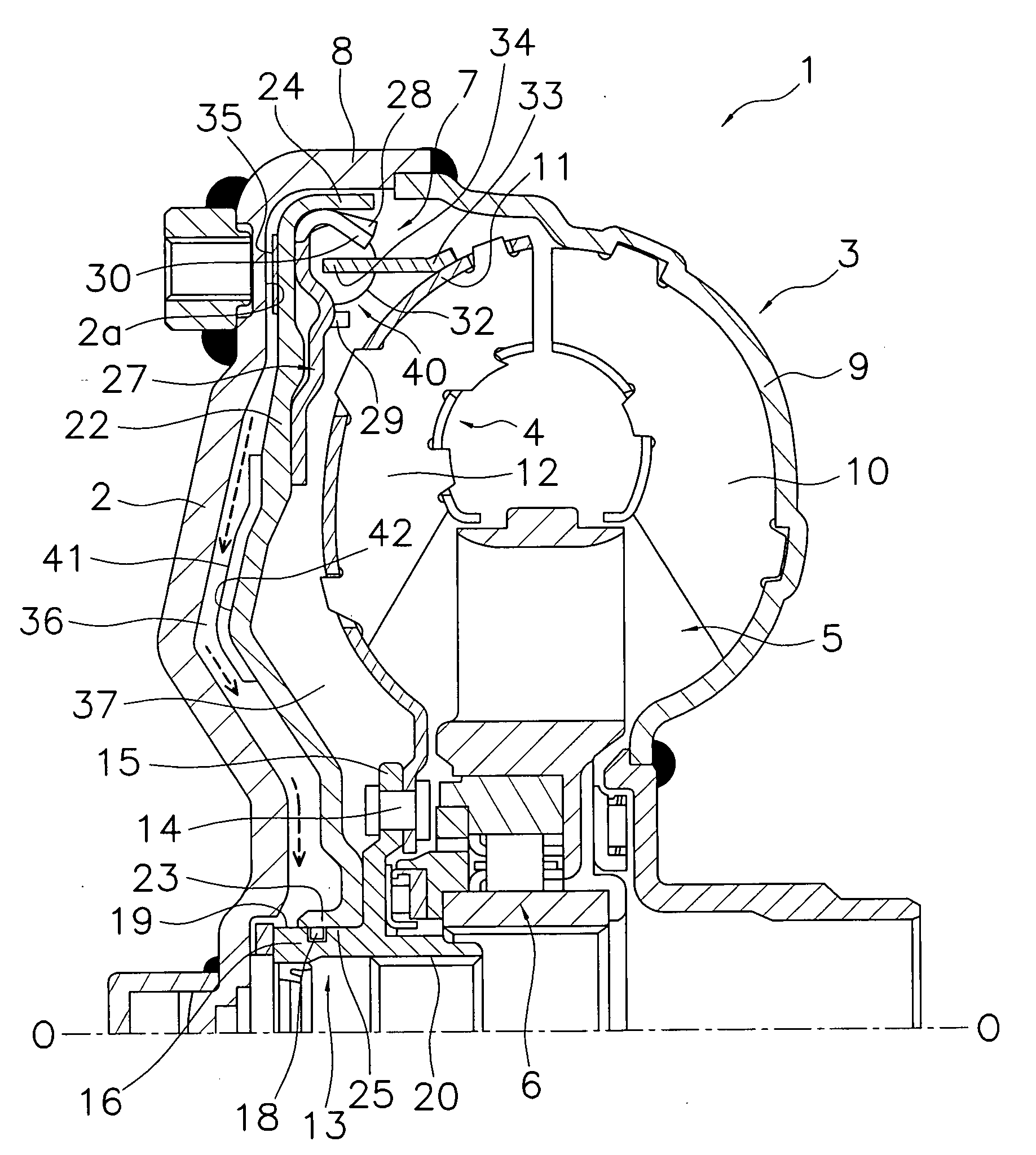
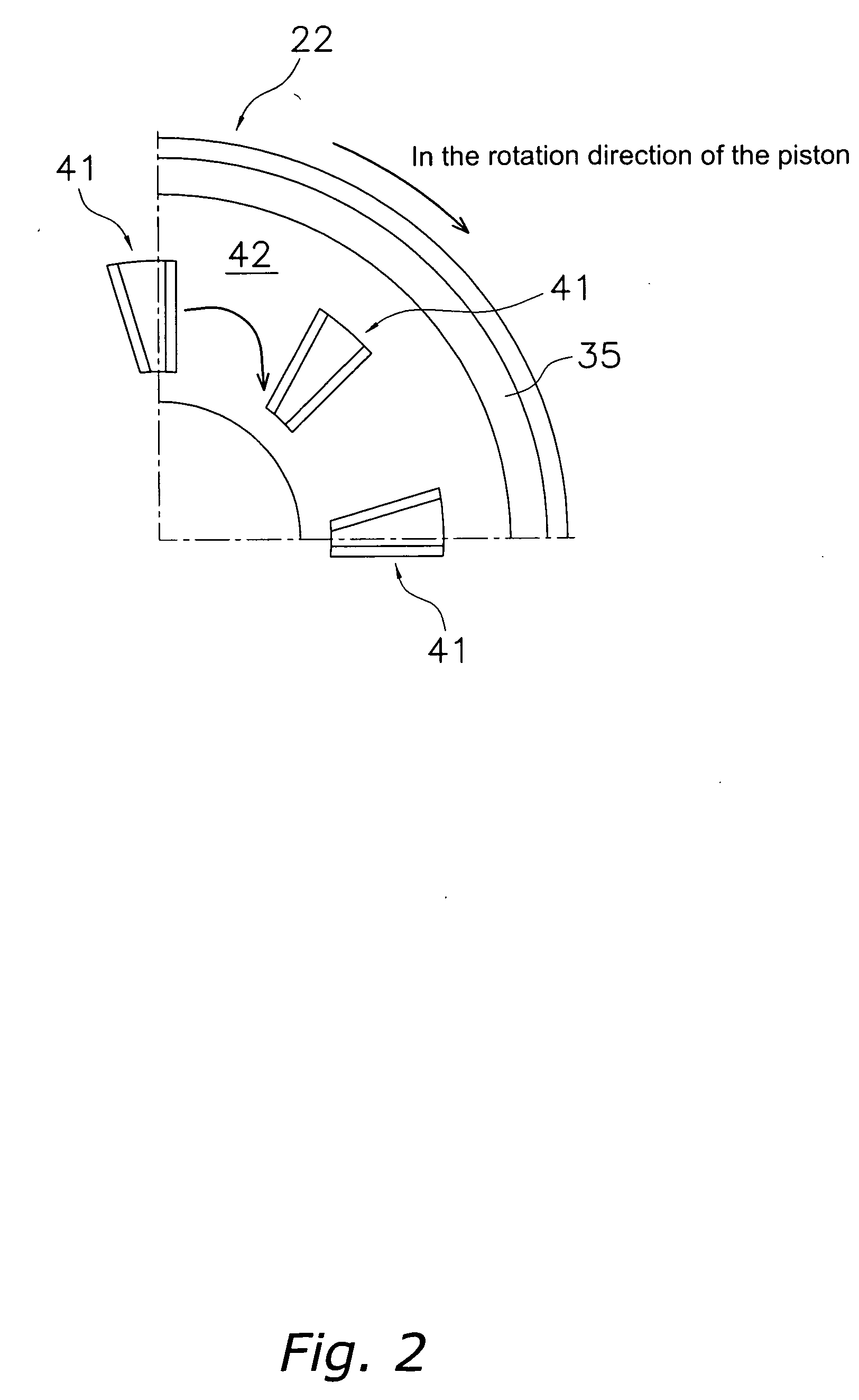
[0070] Performances of the torque converters were compared between the conventional product (without ribs) and a product according to the present invention (with ribs). In FIG. 6, ranges of variation of the capacity factor to the release travels were measured in four cases, more specifically, in two cases in which the input rotation speed was 1500 rpm, and the speed ratios were 0.2 and 0.4, and in two cases in which the input rotation speed was 2000 rpm and the speed ratios were 0.2 and 0.4. The release travels were set to be near 0.3 mm, 0.5 mm, and 0.7 mm. Note that the release travel means a clearance between the friction facing of the piston and the friction surface of the front cover. The sp...

experiment 2

(Experiment 2)

[0072] Changes over time of hydraulic pressures and torque waveforms concerning the responsivity of the lock-up were measured between the conventional product and the product according to the present invention. FIG. 7 shows the results, and FIG. 8 shows positions to be measured of the flow of the working fluid and the responsivity data. Note that the response time of lock-up ON is a time from an instant when signals of the hydraulic pressure are switched to an instant when the torque is started to be generated.

[0073] As is apparent from FIG. 7, in the product according to the present invention responsivity of lock-up ON became faster compared to the conventional product. In the torque converter operating range, the hydraulic pressure on the front cover side (the hydraulic pressure in the first hydraulic chamber 36) of the product according to the present invention was lower than that of the conventional product, and even at an instant when switched to the lock-up ON s...


PUM


Abstract

A lock-up device 7 includes a front cover 2, an impeller 3, a turbine 4, and a piston 22 positioned to divide a space between the front cover 2 and the turbine 4, and is engageable with the front cover 2. The piston 22 is formed with a plurality of projections 41 extending in the radial direction on a surface 42. The projection 41 has a straight front edge 51 and a straight rear edge 52, and an arced radially outer edge 53 and radially inner edge 54. The rear edge 52 in the rotation direction overlaps a straight line Ls connecting a radially inner end 52a with the rotation center O, or the rear edge 52 in the rotation direction is inclined to the straight line Ls such that a radially outer end 52b is positioned rearward of the straight line Ls in the rotation direction.

Description

TECHNICAL FIELD [0001] The present invention relates to lock-up devices of hydraulic torque transmitting apparatuses, particularly, to lock-up devices in which a piston presses itself against a front cover. BACKGROUND ART [0002] Torque converters are apparatuses that transmit torque from the engine to the transmission via a working fluid therein, and mainly include a front cover to which torque is input from the engine, an impeller fixed to a transmission side of the front cover to constitute a fluid chamber therebetween, a turbine located opposite an engine side of the impeller to output the torque to the transmission, and a stator located between a radially inner portion of the impeller and a radially inner portion of the turbine to adjust the flow of the working fluid from the turbine to the impeller. [0003] A lock-up device is located in a space between the turbine and the front cover, and directly transmits the torque from the front cover to the turbine by mechanically engaging...

Claims


Application Information

Patent Timeline
IPC IPC(8): F16H45/02F16H41/26
CPCF16H41/26F16H2045/0294F16H45/02
Inventor KUBOTA, TETSUYA
Owner EXEDY CORP
Why Eureka
Try Eureka