Piezoelectric element, ink jet head and producing method for piezoelectric element

a piezoelectric element and ink jet technology, applied in the direction of printing, generators/motors, coatings, etc., can solve the problems of unsatisfactory compact piezoelectric element, difficult to prepare piezoelectric film with a thickness of 10 m or less, and shrinkage of piezoelectric film to about 70% when heated, etc., to achieve satisfactory durability, high piezoelectric characteristic, and excellent displacement controllability and durability

Inactive Publication Date: 2008-01-17
CANON KK
View PDF8 Cites 28 Cited by
  • Summary
  • Abstract
  • Description
  • Claims
  • Application Information

AI Technical Summary

Benefits of technology

[0014]Consequently, the present invention is to solve the aforementioned problems, and an object thereof is to provide a piezoelectric element having a high piezoelectric characteristic and a satisfactory durability, an ink jet head utilizing the same and excellent in displacement controllability and durability, and a producing method for such piezoelectric element.

Problems solved by technology

However, the PZT type oxide film obtained by this method is difficult to prepare with a thickness of 10 μm or less.
Also since the green sheet is sintered at a temperature of 1000° C. or higher, there results a problem that the piezoelectric film shrinks to about 70% when heated.
As it is difficult to align the piezoelectric film and the structural member such as the ink chamber with a dimensional precision in the order of several micrometers, a satisfactory compact piezoelectric element has not been obtained.
However, such film forming methods as sputtering, CVD process, MBE process or sol-gel process involve a drawback of being incapable of preparing a thin comparable in characteristics to bulk ceramics.
However, even with the method of Japanese Patent Application Laid-Open No.
H08-116103, the characteristics comparable to those of bulk ceramics cannot be obtained at a high electric field side so that the obtained piezoelectric element is insufficient in the performance.
Also the method disclosed in Japanese Patent Application Laid-Open No. 2000-332569 involves drawbacks of being unable to utilize a morphotropic phase boundary range (also represented as MPB range) of satisfactory characteristics and being unable to reproducibly control a proportion of (100) orientation and (001) orientation.
Also in a film having an excessively large proportion of (100) orientation or namely of [100] axis, a contribution of the 90° domain effect becomes large whereby the film becomes inferior in durability in a thin film element.
Also the method of Japanese Patent Application Laid-Open No. 2005-119166 is incapable of controlling (100) orientation and (001) orientation, and is incapable of forming a 90° domain having an anisotropy within the plane of the piezoelectric film.

Method used


Image

  • Piezoelectric element, ink jet head and producing method for piezoelectric element
  • Piezoelectric element, ink jet head and producing method for piezoelectric element
  • Piezoelectric element, ink jet head and producing method for piezoelectric element

Examples


example 3

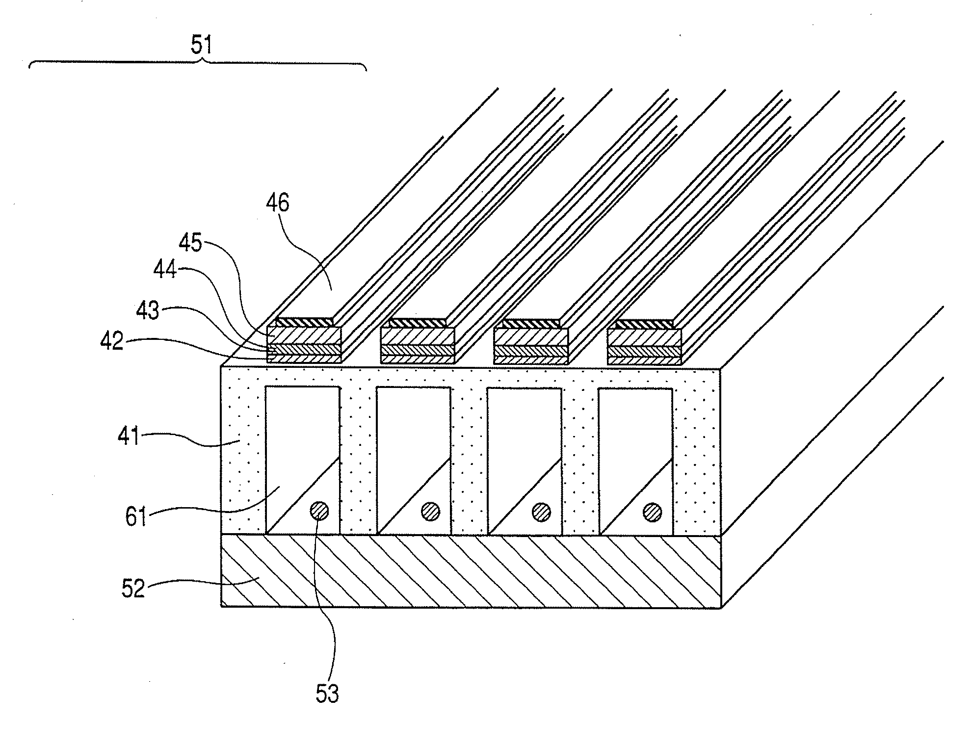
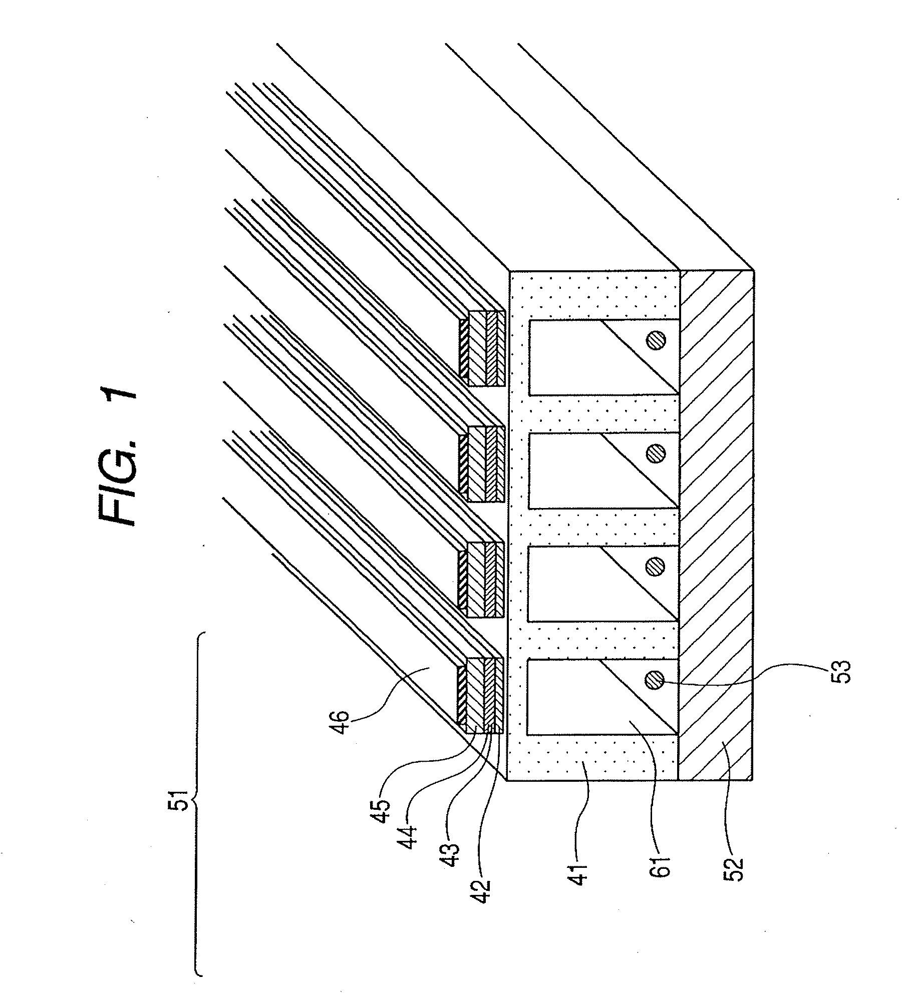
Pt / Ti (Upper Electrode 46) / / PbZrTiO3 (Piezoelectric Member 45) / / SrRuO3 (Lower Electrode 44) / / (LaNiO3 / CeO2 / YSZ (Y2O3—ZrO2) (Buffer Layer 43) / / Si / SiO2 (Vibration Plate 42) / / Si (Substrate 41)

example 4

Pt / Ti (Upper Electrode 46) / / PbZrTiO3 (Piezoelectric Member 45) / / Pt / SrRuO3 (Lower Electrode 44) / / (LaNiO3 / CeO2 / YSZ (Y2O3—ZrO2) (Buffer Layer 43) / / Si / SiO2 (Vibration Plate 42) / / Si (Substrate 41)

[0058]In the foregoing examples, the function noted in each layer often overlaps and does not, therefore, restrict the function.

[0059](Ink Jet Head)

[0060]The ink jet head of the present invention is characterized in including the above-described piezoelectric element of the present invention.

[0061]The ink jet head of the present invention is characterized in including the above-described piezoelectric element of the present invention and is not particularly restricted so far as it includes the piezoelectric element of the present invention, but an exemplary embodiment is illustrated in FIG. 1. The exemplary embodiment of the ink jet head illustrated in FIG. 1 includes a substrate 41, plural pressure chambers (liquid chambers) 61 disposed in a parallel array on the substrate 41, and a liquid disc...

example 1

[0082]An ink jet head of a construction illustrated in FIG. 1 was prepared in the following manner. At first, a sputtering apparatus was used to form, on a Si substrate, in succession an epitaxial stabilized zirconia YSZ (Y2O3—ZrO2) film, an epitaxial CeO2 film and an epitaxial SrTiO3 film, thereby preparing a buffer layer (serving also as a vibration plate).

[0083]In this operation, the epitaxial stabilized zirconia YSZ (Y2O3—ZrO2) film was prepared under conditions of a Si substrate temperature of 800° C., Ar and O2 as process gasses, an electric power of 60 W applied between the Si substrate and the target, and a pressure of 1.0 Pa in the apparatus. Thus an epitaxial stabilized zirconia YSZ (Y2O3—ZrO2) film of a thickness of 200 nm was obtained.

[0084]Also the epitaxial CeO2 film was prepared under conditions of a Si substrate temperature of 800° C., Ar and O2 as process gasses, an electric power of 80 W applied between the Si substrate and the target, and a pressure of 0.5 Pa in t...


PUM


Abstract

A piezoelectric element comprises a piezoelectric film disposed on a substrate and a pair of electrodes disposed in contact with the piezoelectric film and utilizing a bending mode. The piezoelectric film includes domains constituted of a tetragonal crystal and including an a-domain which is formed by a crystal having a (100) plane parallel to the film surface of the piezoelectric film, the a-domains include an A-domain having a normal axis of (001) plane substantially parallel to a principal bending direction of the piezoelectric film and a B-domain having a normal axis of (001) plane substantially perpendicular to the principal bending direction of the piezoelectric film, and the A-domains have a volume proportion larger than 50 vol % with respect to the sum of the volume of the A-domains and the volume of the B-domains.

Description

BACKGROUND OF THE INVENTION[0001]1. Field of the Invention[0002]The present invention relates to a piezoelectric element and an ink jet head, for use in an ink jet recording apparatus, and to a producing method for a piezoelectric element.[0003]2. Description of the Related Art[0004]The piezoelectric element is an element capable of converting an electric energy into a mechanical energy such as mechanical displacement, stress or vibration, and also of a reverse conversion, and is available for example in unimorph type and bimorph type, depending on the generated bending displacement. Such piezoelectric element is widely utilized for example in an ink jet head of an ink jet recording apparatus, a microphone, a sound generating device (such as a speaker), various vibrators, oscillators and sensors. Recently, a printer utilizing an ink jet head is widely utilized as a printing apparatus of personal computers and the like, because of a satisfactory printing performance, an easy handling...

Claims


Application Information

Patent Timeline
Patent Type & Authority Applications(United States)
IPC IPC(8): B41J2/045B05D5/12H01L41/09H01L41/22
CPCB41J2/14233B41J2/161B41J2/1628B41J2/1629H01L41/316B41J2/1646H01L41/0815H01L41/0973H01L41/1876B41J2/1642H10N30/10516H10N30/2047H10N30/8554H10N30/076
Inventor MATSUDA, TAKANORIIFUKU, TOSHIHIROTAKEDA, KENICHIAOKI, KATSUMI
Owner CANON KK
Why Eureka
Try Eureka