Probe for scanning over a substrate and a data storage device
a technology for scanning devices and substrates, applied in nanoinformatics, mechanical recording, instruments, etc., can solve problems such as the temperature of the probe, and achieve the effects of reducing the amount of heat lost, reducing the mass to be heated, and reliable operation of the prob
- Summary
- Abstract
- Description
- Claims
- Application Information
AI Technical Summary
Benefits of technology
Problems solved by technology
Method used
Image

Examples
first embodiment
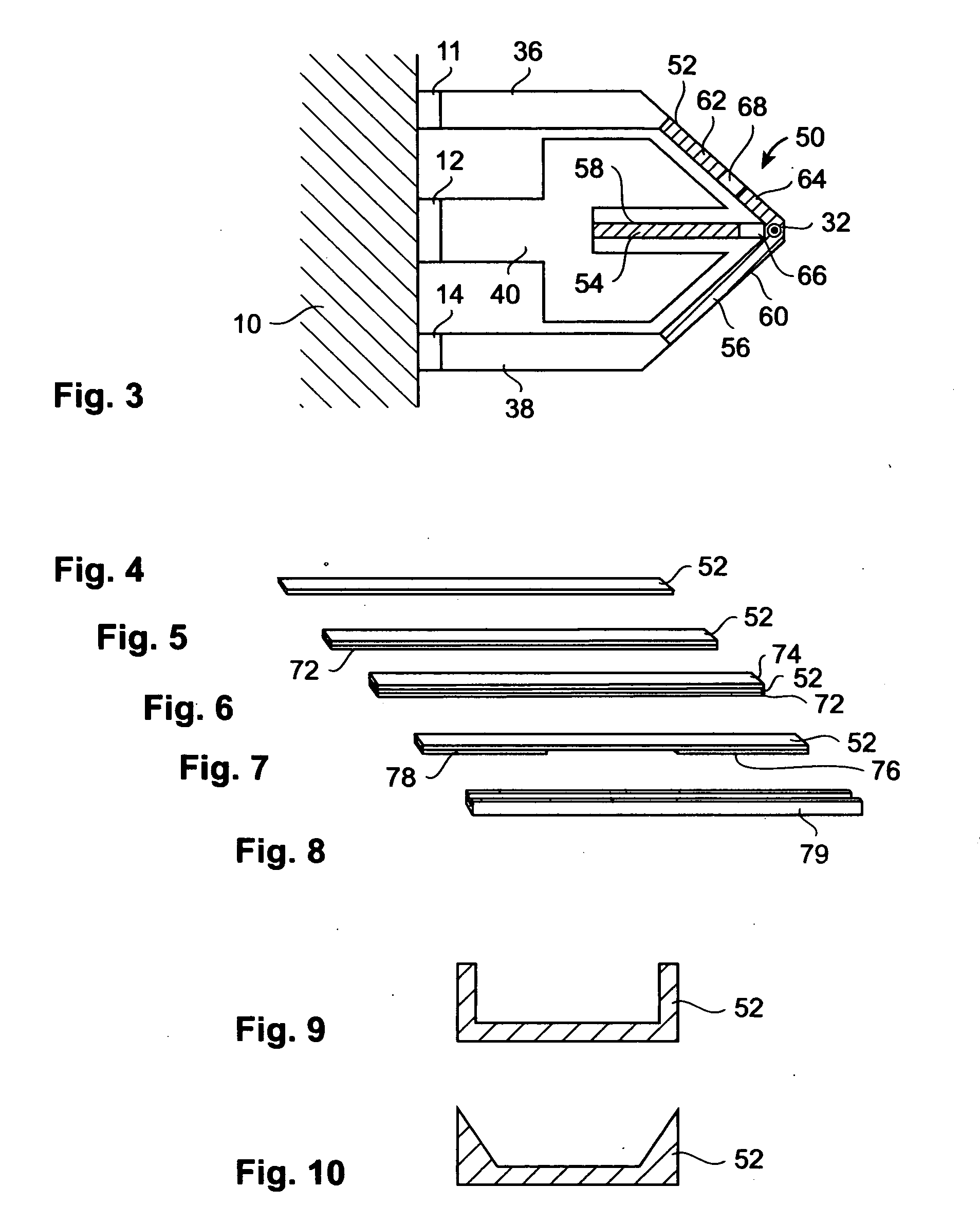
[0058] The probe 8 comprises coupling elements, also referred to as hinges 42, 44, 46,48 (FIG. 12) which abut to the first to third terminals 11, 12, 14. The hinges 42 to 48 mechanically couple a supporting structure with the terminals 11, 12, 14 and in that way with the frame 10. The supporting structure extends away from the hinges and comprises legs 36, 38 and may comprise a capacitive platform 40. The supporting structure may also directly abut the terminals 11, 12, 14. The hinges 42, 44, 46, 48 serve the purpose of setting a spring constant for the spring cantilever. The probe further comprises a beam structure 50, which comprises the first and second heating resistors 66, 68. In a simpler embodiment the probe 8 may also comprise only one heating resistor, which is then used for the writing mode and the read mode. In the probe 8 according to FIG. 3 the beam structure 50 comprises first to third beams 52, 54, 56. The beams are arranged in an arrow-like shape and are attached to ...
third embodiment
[0064] The thickness of the beams 52,54,56 of the beam structure 50 is substantially less than the respective thickness of the supporting structure, which can be seen by the representation of the probe in FIG. 12 but is also the case for the other embodiments of the probe. The thickness of the beam structure may for example be less than one-fifth of the respective thickness of the supporting structure.
[0065] An effective heating resistor distance within the beam structure from a respective heating resistor 66, 68 is given by the distance resulting when going through the material of the beam structure 50 towards the respective ends of the beam structure 50. This effective heating resistor distance is characteristic for an amount of heat which may be conducted into the supporting structure. In order to minimize a heat loss into the supporting structure the effective heating resistor distance is chosen to be longer than or equal to half of an effective temperature decay length λ or lon...
second embodiment
[0075] In the probe 8 (FIG. 11) the beam structure 50 is mechanically reinforced by reinforcement bridges 82, 84, 86, that are attached to the beam structure 50 and to the supporting structure. The reinforcement bridge 82 is attached on one of its ends to the third lead 62 and on its other end to the capacitive platform 40. The reinforcement bridge 84 has three ends, two of which are attached to the capacitive platform 40 and one end in the middle, which is attached to the second beam 54. The reinforcement bridges 82, 84, 86 should be formed of a material which is electrically insulating in order to prevent short-cutting of the respective heating resistors 66, 68. However, depending on where the respective reinforcement bridge is attached to, this may not be a necessary property, as is the case for the reinforcement bridge 84. The reinforcement bridges 82, 84, 86 should however be thermally insulating.
[0076]FIG. 12 shows a third embodiment of the probe 8. The beam structure comprise...
PUM
 Abstract
Description
Claims
Application Information
 - R&D
- Intellectual Property
- Life Sciences
- Materials
- Tech Scout
- Unparalleled Data Quality
- Higher Quality Content
- 60% Fewer Hallucinations
Browse by: Latest US Patents, China's latest patents, Technical Efficacy Thesaurus, Application Domain, Technology Topic, Popular Technical Reports.
© 2025 PatSnap. All rights reserved.Legal|Privacy policy|Modern Slavery Act Transparency Statement|Sitemap|About US| Contact US: help@patsnap.com