Network Processor System and Network Protocol Processing Method

a network processor and network protocol technology, applied in the field of network processor systems and network protocol processing methods, can solve the problems of difficult processing of microprocessors, bottlenecks in network bandwidth, and inability to improve the processing performance of microprocessors that process packets transmitted through the network

Active Publication Date: 2008-01-17
SONY COMPUTER ENTERTAINMENT INC
View PDF8 Cites 64 Cited by
  • Summary
  • Abstract
  • Description
  • Claims
  • Application Information

AI Technical Summary

Benefits of technology

[0015]Accordingly, a general purpose of the present invention is to provide an efficient communication technology that necessitates RDMA functionality.

Problems solved by technology

On the other hand, it is a current status that the processing performance of a microprocessor that processes packets transmitted through the network has not improved as much as the network performance.
Therefore it is difficult for the microprocessor to process the packet transmitted through a high-speed network at a sufficient speed.
Particularly, the processing performance of the microprocessor will become a bottleneck for the network bandwidth when the bandwidth of the network exceeds around one Giga bit per second (Gbps).
The TCP processing as listed above is composed of some processes that require a large amount of computation such as checksum and retransmission, resulting in putting a heavy load on the processor.
Since the context switch produces overhead, it will become a bottleneck for the overall processing performance.
This memory-to-memory copy produces some overhead.
The conventional network interface cards that have been used in a normal situation are useless to utilize the RDMA.
It costs a lot to replace all existing NICs by RNICs conforming to RDMA.
This is a cause that the spread of the RDMA technology has been delayed.
Furthermore, if only a part of network interface cards are replaced by RDMA-enabled cards and the network is configured in such a manner that the conventional NICs and the RNICs coexist, another problem might occur in which the communication between the conventional NICs and the RNICs becomes impossible.

Method used


Image

  • Network Processor System and Network Protocol Processing Method
  • Network Processor System and Network Protocol Processing Method
  • Network Processor System and Network Protocol Processing Method

Examples


first embodiment

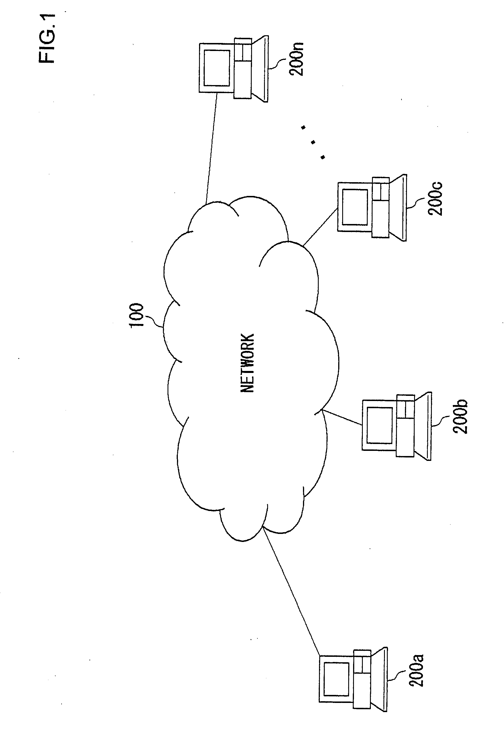
[0042]FIG. 1 shows a network system according to an embodiment of the present invention. A plurality of nodes 200a, 200b, 200c, . . . , and 200n are connected to a network 100. The nodes connected to the network 100 are hereinafter collectively or individually referred to as a node 200. The network 100 includes a router that transfers packets according to Internet Protocol (IP).

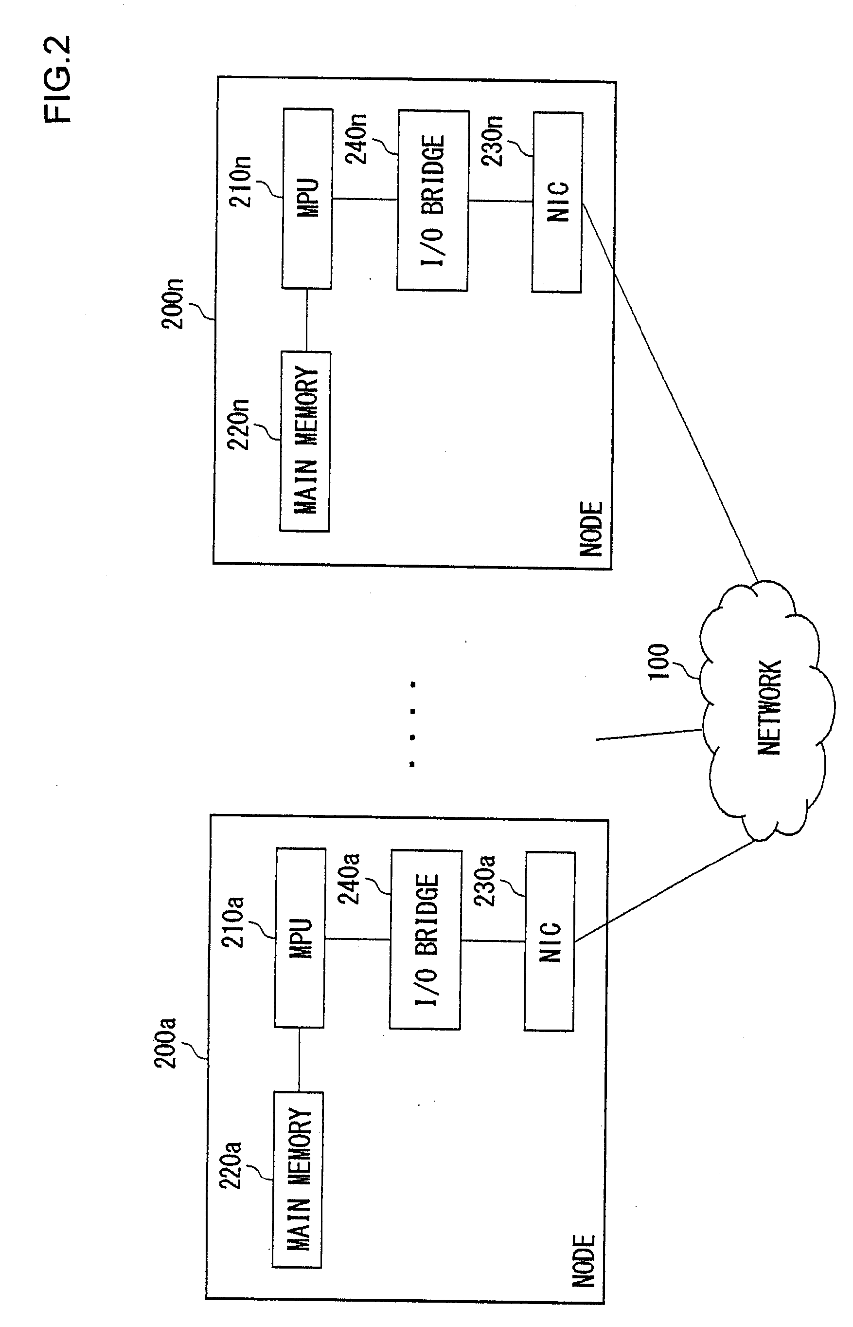
[0043]FIG. 2 is a block diagram of the node 200 of FIG. 1. Each node 200 includes a micro processing unit (MPU) 210, a main memory 220, an I / O bridge 240, and a network interface card (NIC) 230.

[0044]The MPU 210 generates a packet in which a header information such as a destination address is added to data to be transmitted stored in the main memory 220. The MPU 210 passes the packet thus generated to a buffer in the NIC 230 through the I / O bridge 240. The NIC 230 sends out the packets stored in the buffer to the network 100.

[0045]The NIC 230 stores a packet received from the network 100 in the buffer and the...

first embodiment example

[0059]FIG. 4 is a block diagram of the node 200 according to the first embodiment example. In the first embodiment example, the node 200 is equipped with a normal TOE-less NIC 30 and the NIC 30 is enabled to operate by the configuration on startup of the system. Here, the structure related to the TOE-NIC 31 that does not operate is not shown in the figure. In the first embodiment example, the TCP / IP protocol stack is implemented on the PU 10 or the SPU 20. The TCP / IP protocol stacks 10s, 20s respectively implemented on the PU 10 and the SPU 20 can operate simultaneously or either of these stacks may pause.

[0060]As an example of RDMA operations, a RDMA write is now explained. Assumes that a RDMA write is executed between the two nodes 200a and 200b of FIG. 1. The source node 200a issues a RDMA write command to the destination node 200b so as to transmit data to be RDMA written to the destination node 200b.

[0061]FIG. 5 is a sequence diagram of a RDMA write process executed between th...

second embodiment example

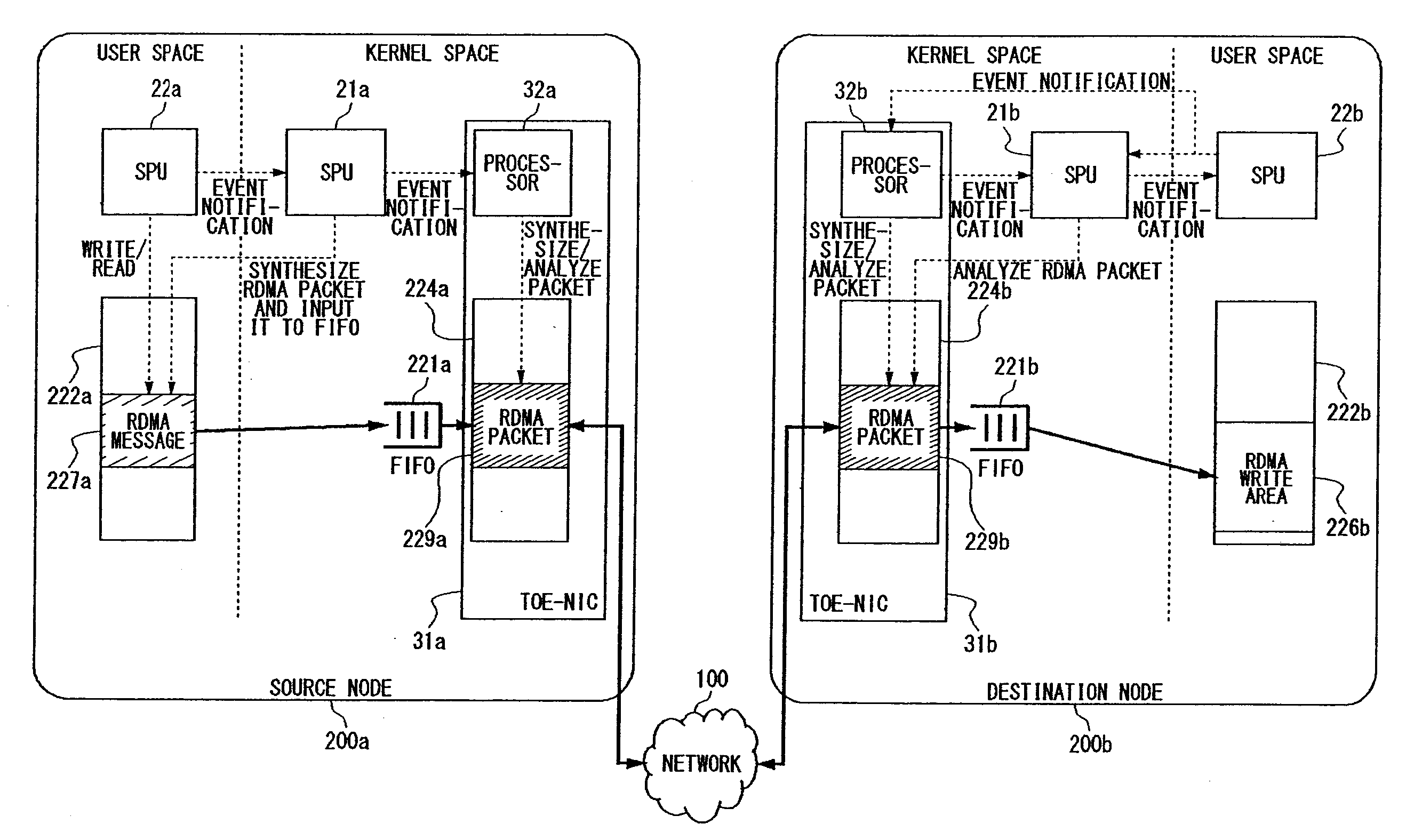
[0094]FIG. 8 is a block diagram of the node 200 according to the second embodiment example. In the first embodiment example, the case has been explained in which the node 200 is equipped with the normal NIC 30 with no TOE function. In the second embodiment example, the case will be explained in which the node 200 is equipped with the TOE-NIC 21 having a TOE function. Since the configuration on startup of the system enables the TOE-NIC 21 to operate, any structure related to the NIC 30 that does not operate is not shown in the figure. Since a TCP / IP protocol stack is implemented in the TOE-NIC 31, the TCP / IP protocol processing can be performed inside the TOE-NIC 31.

[0095]In the second embodiment example, the operation will be described for the case in which a RDMA write is executed between the source node 200a and the destination node 200b as in the first embodiment example. The sequence of the RDMA write process between the source node 200a and the destination node 200b is the same...


PUM


Abstract

A multiprocessor system is provided for emulating remote direct memory access (RDMA) functions. The first sub-processing unit (SPU) generates a message to be transmitted. The second SPU is a processor for emulating the RDMA functions. Upon receiving a notification from the first SPU, the second SPU synthesizes the message into a packet according to a RDMA protocol. The third SPU is a processor for performing a TCP / IP protocol processing. Upon receiving a notification from the second SPU, the third SPU synthesizes the packet generated according to the RDMA protocol into a TCP / IP packet and then sends it out from a network interface card.

Description

BACKGROUND OF THE INVENTION[0001]1. Field of the Invention[0002]The present invention relates to a network processor system and a network protocol processing method.[0003]2. Description of the Related Art[0004]Recent advances in network technology promote the wide use of Gigabit network so that the bandwidth of the network has remarkably expanded. On the other hand, it is a current status that the processing performance of a microprocessor that processes packets transmitted through the network has not improved as much as the network performance. Therefore it is difficult for the microprocessor to process the packet transmitted through a high-speed network at a sufficient speed. Particularly, the processing performance of the microprocessor will become a bottleneck for the network bandwidth when the bandwidth of the network exceeds around one Giga bit per second (Gbps).[0005]There are the following three causes that the processing performance of the processor will become a bottleneck...

Claims


Application Information

Patent Timeline
Patent Type & Authority Applications(United States)
IPC IPC(8): G06F11/00
CPCG06F13/105H04L49/90H04L49/901H04L69/32H04L49/9073H04L67/1097H04L49/9063H04L69/326
Inventor HORIE, KAZUYOSHITACHIBANA, KAZUTAKATANAKA, TAKU
Owner SONY COMPUTER ENTERTAINMENT INC
Why Eureka
Try Eureka