Storm drain basin gate system

a storm drain basin and gate technology, applied in the field of gate systems, can solve the problem of insufficient and achieve the effect of reducing the water weight on the trip pla

Inactive Publication Date: 2008-01-17
FLURY RONALD J
View PDF7 Cites 31 Cited by
  • Summary
  • Abstract
  • Description
  • Claims
  • Application Information

AI Technical Summary

Benefits of technology

[0010] The invention herein depicted and describes provides such a device wherein the gate portion of the system that prevents trash from entering into the vault or drain basin is kept in the closed position by virtue of a trip plate that is rotatably attached to the back of the gate. The trip plate is attached to back lower portion of the gate, and is biased (in the preferred embodiment by a spring) to an “up” position (that is, substantially perpendicular in the preferred embodiment) relative to the gate. The trip plate is prevented from moving backward (that is, away from the gate), which in the preferred embodiment is accomplished by two pins extending from the plate into a groove formed in each of a pair of brackets that are attached to the drain basin wall. Thus, when there is no-flow or low-flow of water through the gate onto the trip plate, the plate stays in position and in turn keeps the gate in a close position, flush against the drain basin opening. When the flow of water increases to a predetermined point, however, the water weight on the trip plate increases to the point where the upward biasing is overcome, and the trip plate rotates downward. This releases the gate and allows it to open. When the water flow onto the trip plate stops or reduces to a sufficiently low flow, the water weight on the trip plate is no longer sufficient to overcome the upward biasing on the plate, and it rotates back into its “up” position, which in turn causes the gate to rotate downward into its “closed” position against the drain basis opening. Also disclosed and claimed are improved and alternative apparatus for attaching the system to the storm drain basin, and for holding controlling the location of the trip plate.

Problems solved by technology

When the water flow onto the trip plate stops or reduces to a sufficiently low flow, the water weight on the trip plate is no longer sufficient to overcome the upward biasing on the plate, and it rotates back into its “up” position, which in turn causes the gate to rotate downward into its “closed” position against the drain basis opening.
As will be apparent to those skilled in the art, however, there are many different ways of attaching the various components of this system to the basin, and to one another, and of creating the biasing of the trip plate, and there are too many different ways to do so to list and describe here.

Method used


Image

  • Storm drain basin gate system
  • Storm drain basin gate system
  • Storm drain basin gate system

Examples


Embodiment Construction

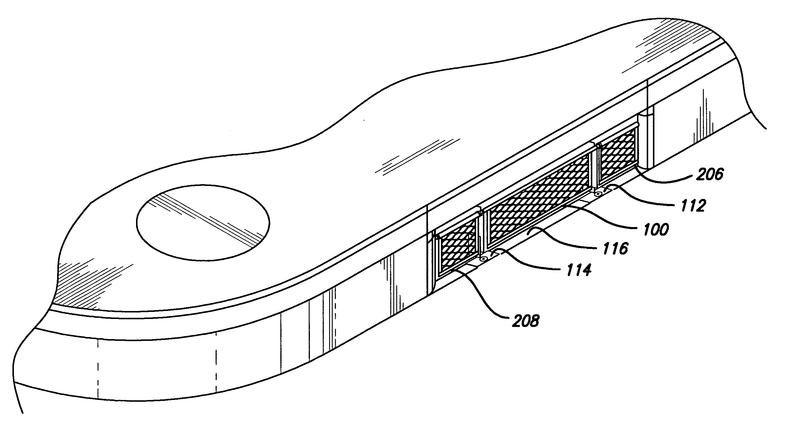
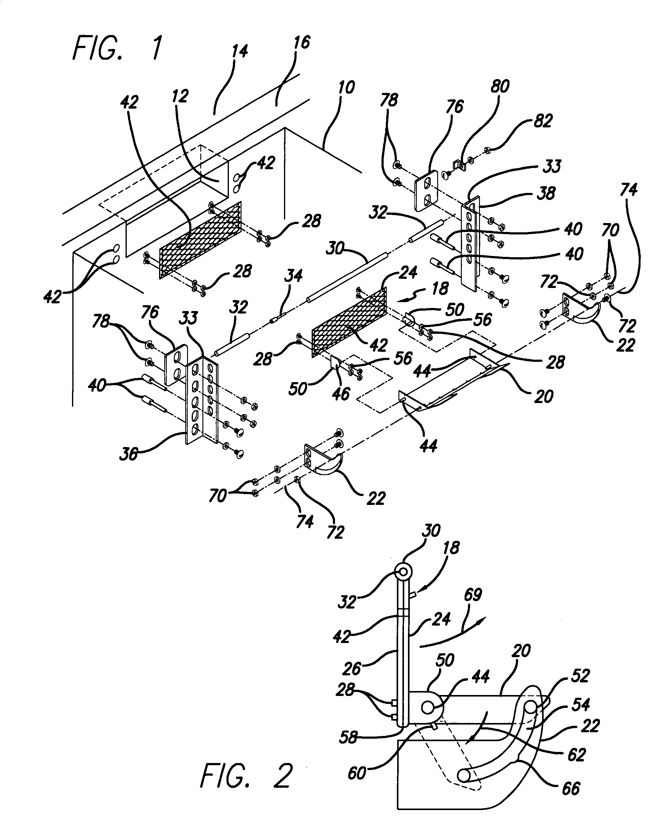
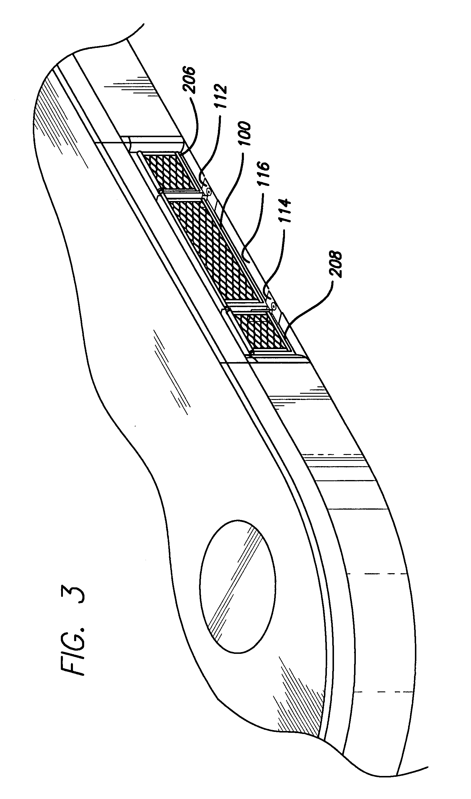
[0018] Looking at FIG. 1, it is seen that the preferred embodiment of this invention is for attachment to the inside of a curb-side storm drain basin 10, adjacent to and providing a cover for the opening 12 that leads from the basin 10 to the street 14 through the curb 16. It should be noted, however, that while the device of this invention is believed to find primary utility in this application, and is why the title of this invention includes a reference to a storm drain, the invention herein described and claimed is a gate system that is not limited to that one application. The device of this invention could be usefully applied to any situation where it is desired to screen particulate matter from a fluid flow through an aperture during no-flow and low-flow conditions, but to remove the screen from the aperture during high-flow conditions.

[0019] The overall system consists primarily of a gate assembly 18, the biased trip plate 20, trip plate brackets 22, and the various means by ...


PUM


Abstract

An automatically openable and closeable gate system that will find primary use with the street curb opening to a catch basin or vault of a storm drain system, and for other similar openings, the system having a gate which during dry and low-flow water drainage situations will be in a closed position such that items of trash, debris, litter, leaves and the like will be prevented from entering the basin, vault or system, yet in periods of heavy rainfall or other heavy water run-off situations will automatically open to allow free flow of water into the basis or vault to alleviate water accumulation in the adjacent street and other surrounding areas.

Description

CROSS REFERENCE TO RELATED APPLICATIONS [0001] This application is a continuation-in-part of U.S. Ser. No. 11 / 335,591, entitled Storm Drain Basis Gate System, soon to be issued U.S. Pat. No. 7,234,894, issue date Jun. 26, 2007.BACKGROUND OF THE INVENTION [0002] This invention relates generally to a gate system for use with a storm drain of the type typically found in the curb of a street. More particularly, this invention relates to such a system which during periods of low water flow is in a closed position to effectively prevent debris from entering into the storm drain, but which during periods of high water flow opens to allow the maximum amount of water to enter into the drain to alleviate the accumulation of water in the street and the surrounding areas. [0003] What to do with excess runoff rain water has been an issue for urban planners and dwellers for a long time. Even in arid regions, the occasional heavy rainfall will create large volumes of run off that must be channeled...

Claims


Application Information

Patent Timeline
Patent Type & Authority Applications(United States)
IPC IPC(8): E02B7/40
CPCE03F1/00E03F5/046E03F5/0404
Inventor FLURY, RONALD J.
Owner FLURY RONALD J
Why Eureka
Try Eureka