Transmission power control method for a wireless communication system

a technology of transmission power and communication system, applied in power management, high-level techniques, sustainable buildings, etc., can solve problems such as omission of received data, lowering of communication channel capacity, and inability to obtain stable communication quality, so as to prevent the increase of average transmission power

Inactive Publication Date: 2008-01-17
HITACHI LTD
View PDF17 Cites 31 Cited by
  • Summary
  • Abstract
  • Description
  • Claims
  • Application Information

AI Technical Summary

Benefits of technology

[0007] It is therefore a first object of the present invention to provide a transmission power control method for attaining a desired reception quality while preventing increase in average transmission power even when there occurs a propagation path gain variation having a comparatively short period of time.
[0008] In addition, when the average transmission power is not increased, average received power is reduced. The deterioration of the reception quality (SN ratio or SNR) caused by the reduction results in lowering in the capacity of the communication channel. That is, the maximum data rate at which communication can be made is lowered. It is therefore a second object of the present invention to keep the communication channel capacity as large as possible even when there occurs a propagation path gain variation having a comparatively short period of time.
[0009] In addition, when the communication channel capacity per time varies due to a variation of the propagation path gain, there is a problem that the time required for making communication for desired information varies so that stable communication quality cannot be obtained. It is therefore a third object of the present invention to provide stable communication quality even when the communication channel capacity per time varies.

Problems solved by technology

The deterioration of the reception quality (SN ratio or SNR) caused by the reduction results in lowering in the capacity of the communication channel.
In addition, when the communication channel capacity per time varies due to a variation of the propagation path gain, there is a problem that the time required for making communication for desired information varies so that stable communication quality cannot be obtained.
Further, if the transmission power is reduced when the propagation path gain is low, there may occur dispersion in quality of Received Data or omission in the Received Data.

Method used


Image

  • Transmission power control method for a wireless communication system
  • Transmission power control method for a wireless communication system
  • Transmission power control method for a wireless communication system

Examples


Embodiment Construction

[0045] First, description will be made on a power control algorithm according to the present invention.

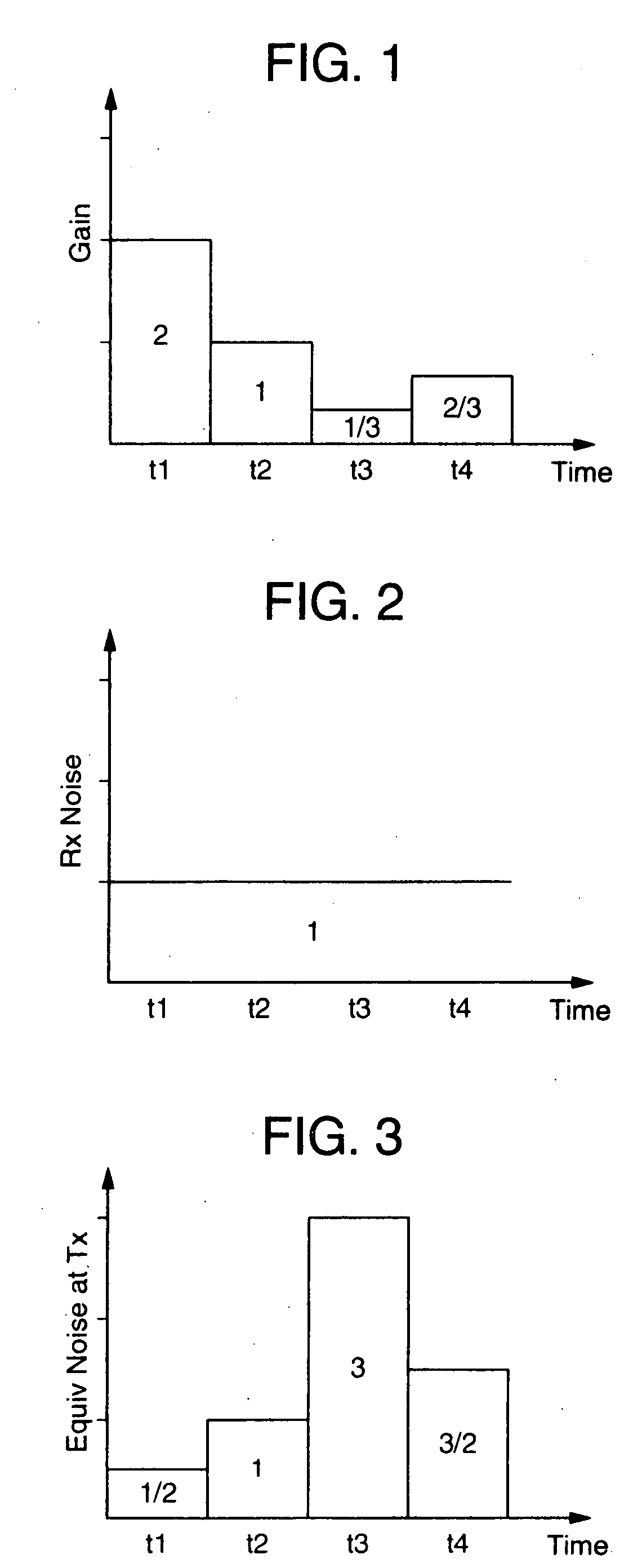
[0046]FIG. 1 is a graph showing an example of a time variation of a 10 propagation path gain. Now, consider that the propagation path gain has a variation as shown in FIG. 1. That is, consider a propagation path in which gains at time instants t1, t2, t3 and t4 are 2, 1, 1 / 3 and 2 / 3 respectively so that the average gain is 1.

[0047]FIG. 2 is a graph showing an example of a time variation of noise power.

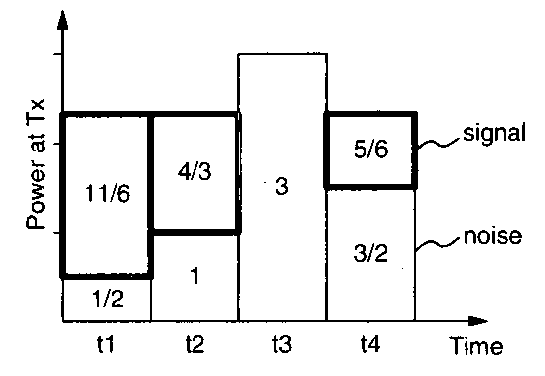
[0048]FIG. 3 is a graph showing an example of a time variation of equivalent noise power at a transmitter. Assume that constant noise with power of 1 is added on the reception side as shown in FIG. 2. This is equivalent to the case where noises of powers 1 / 2, 1, 3 and 3 / 2 are added on the transmission side at the time instants t1, t2, t3 and t4 respectively as shown in FIG. 3. That is, a variation of the propagation path gain can be regarded as a variation of noise power equivalent...


PUM


Abstract

Transmission power relative to a propagation path having a variation in gain is controlled to increase communication channel capacity, and a data rate is controlled in accordance with the variation of the increased communication channel capacity. In order to increase the communication channel capacity, the transmission power is determined so that the sum of noise power (=received noise power / propagation path gain) converted into one at a transmitter and the transmission power becomes constant. As a result, contrary to the background art, the transmission power is controlled to be reduced when the propagation path gain decreases and to be increased when the propagation path gain increases.

Description

[0001] The present application is a continuation of application Ser. No. 11 / 812,693, filed Jun. 21, 2007; which is a divisional of application Ser. No. 10 / 287,676, filed Nov. 5, 2002, the contents of which are incorporated herein by reference.BACKGROUND OF THE INVENTION [0002] The present invention relates to a method for controlling wireless transmission power and a communication channel data rate in a wireless communication system, and particularly preferably applied to a mobile communication system. [0003] In wireless communication systems, there are known techniques for controlling transmission power of a Wireless Communication Station in order to obtain a desired reception quality. For example, U.S. Pat. No. 5,267,262, Qualcomm Inc., “Transmitter Power Control System” discloses a technique in a CDMA mobile communication system as follows. That is, signal received power from each mobile station is measured in a base station. When the measured signal received power is lower than ...

Claims


Application Information

Patent Timeline
Patent Type & Authority Applications(United States)
IPC IPC(8): H04Q7/20H04B7/26H04B7/005H04B17/40H04W52/08H04W52/24H04W52/26H04W52/44
CPCH04W52/243H04W52/242Y02B60/50H04W52/50H04W52/247Y02D30/70H04W52/24
Inventor YANO, TAKASHITAMAKI, SATOSHI
Owner HITACHI LTD
Why Eureka
Try Eureka