Surgical endoscopic cutting device and method for its use

a cutting device and endoscope technology, applied in the field of surgical endoscope cutting devices, can solve the problems of high-frequency electric current leading to internal and external burns, high-risk electrolyte displacement, and high time-consuming operations

Inactive Publication Date: 2008-01-17
TYCO HEALTHCARE GRP LP
View PDF84 Cites 131 Cited by
  • Summary
  • Abstract
  • Description
  • Claims
  • Application Information

AI Technical Summary

Benefits of technology

[0011] According to the invention, a further outlet channel is provided, the function of which is independent of whether or not detached tissue has been released. In other words, a regular discharge of fluid can occur through this further outlet channel. Since only a minor part of the fluid is now discharged through the outlet, in which there are detached pieces of tissue, the pressure inside the body cavity can be regulated and controlled accurately. This makes it possible to remove undesired tissue from cavities such as the uterus. The applicability of the removal of tissues by cutting is consequently considerably increased.
[0014] Discharge of the tissue material which has been detached can be achieved either by making the stem on which the cutting elements are fitted hollow, or by fitting a protective tube around the cutter. Such a protective tube can also be used without the space between protective tube and stem serving as an outlet channel. This means that the cutter can be designed as a separate unit which can be coupled to the rigid housing, which has advantages in particular for purposes of sterilization. Namely, the device can then be detached in a simple way.

Problems solved by technology

This can lead to highly dangerous electrolyte displacements.
It has been found that the tissue can be removed more easily by working with a high-frequency monopolar electric current, but there is a risk of high-frequency electric current leading to internal and external burns.
This means that such operations are very time-consuming and require the surgeon to repeatedly move the device back and forth.
This is tiring and consequently difficult to learn.
It is not uncommon for such an operation to be broken off because the patient's life is endangered by the side effects.
However, in the case of other body cavities, it is necessary to “blow up” the cavity before treatment can be carried out.
The irregular discharge of fluid through the hollow stem of the cutter, caused partly by the irregular release of tissue, means that it cannot be guaranteed that the pressure inside the cavity is accurately controlled.
Such a device is consequently not very suitable for use in the treatment of such a cavity.

Method used


Image

  • Surgical endoscopic cutting device and method for its use
  • Surgical endoscopic cutting device and method for its use
  • Surgical endoscopic cutting device and method for its use

Examples


Embodiment Construction

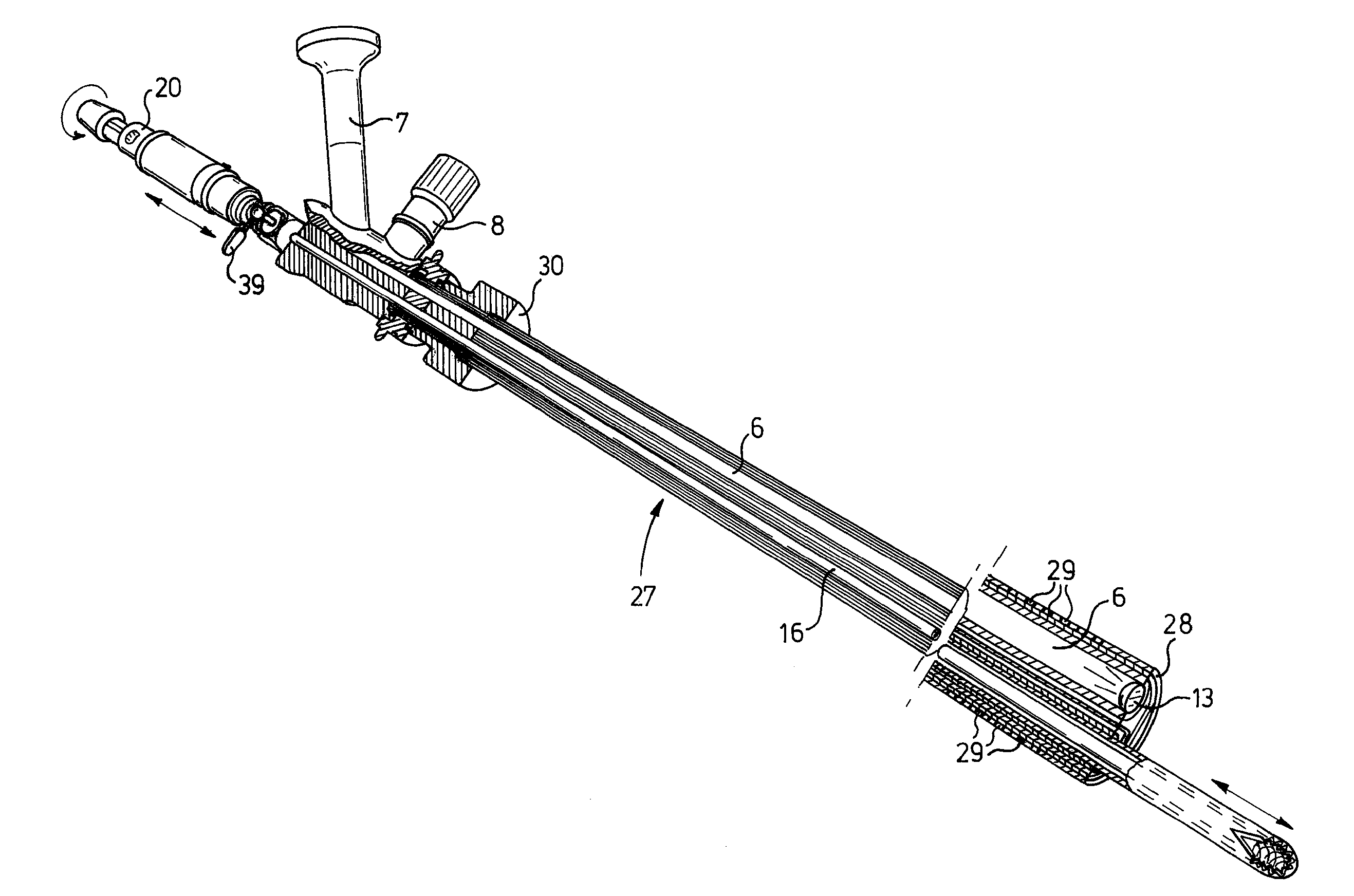
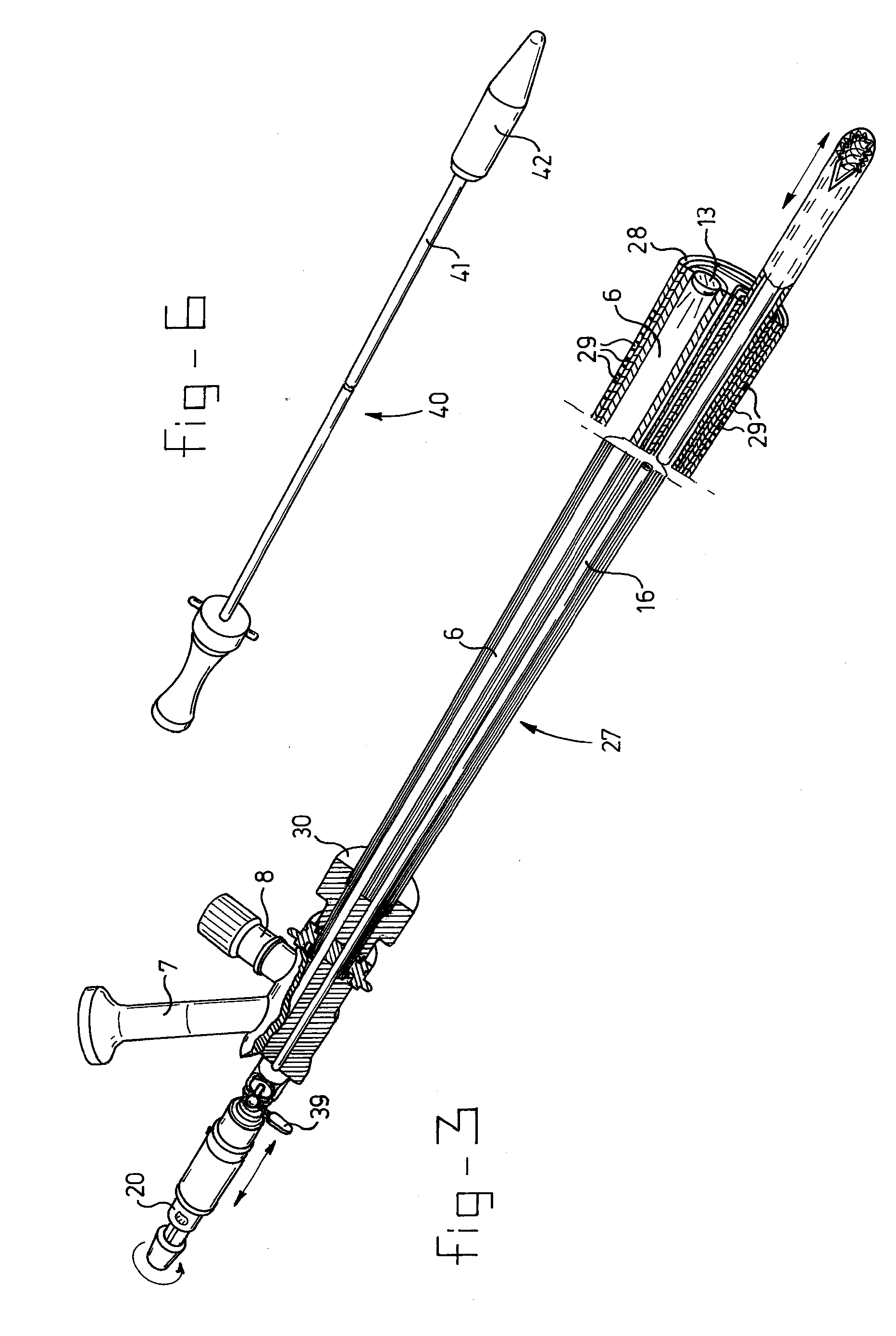
[0028] The endoscopic cutting device according to the invention is indicated in its entirety by 1 in FIG. 1. It comprises a viewing / receiving part 3, which is shown in FIG. 2, a cutting part 2, which is shown in greater detail in FIGS. 4 and 5, and an insertion mandrel, which is shown in FIG. 6.

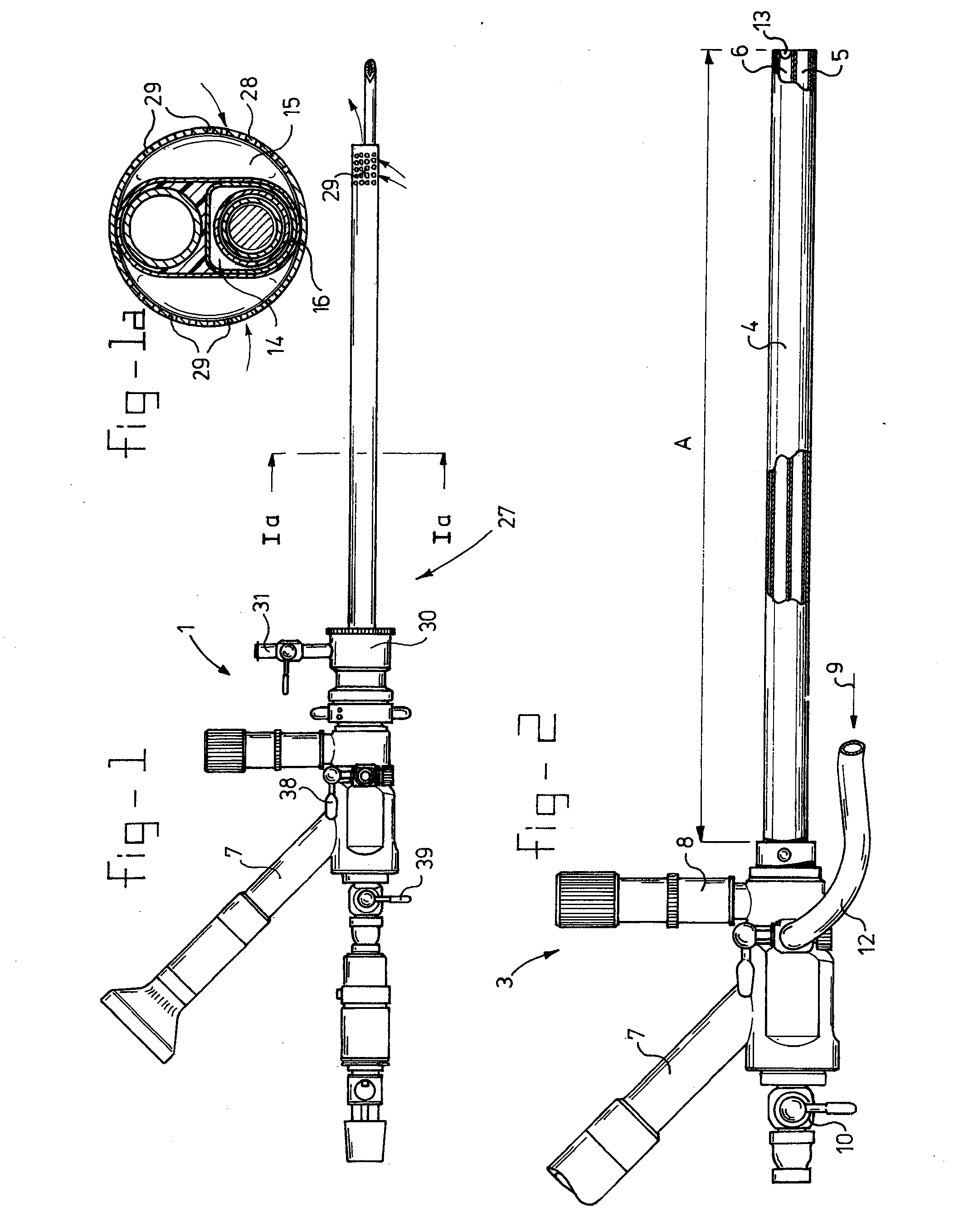
[0029] With reference to FIG. 2, it can be seen that the viewing / receiving part 3, is composed of an outer tube 4 in which a main channel 5 and viewing channel 6 are defined. Viewing channel 6 ends at one side in a lens 13 and at the other side in a viewing tube 7, on which an eyepiece or camera connection is placed. A connection 8 for a light source is also present, for connection to a fibre optics bundle which provides for lighting at the end of lens 13. Near the control end, tube 4 is provided with a fluid inlet 9 connected to a hose 12, for adding a physiological salt solution.

[0030] A shut-off valve is indicated by 10.

[0031] The length of the actual outer tube 4, is indicated by A and...


PUM


Abstract

A surgical endoscopic cutting device includes cutting elements fitted in a protective tube. The device has an inlet for fluid, a discharge outlet for tissue and fluid, and a further outlet that discharges most of the fluid.

Description

FIELD OF THE INVENTION [0001] The present invention relates to a surgical endoscopic cutting device. BACKGROUND OF THE INVENTION [0002] Surgical cutting devices are generally known and used for the removal of hard and / or soft tissue, such as in the vicinity of the knee joint. Such cutting devices are used in, for example, a joint cavity, where they can be guided endoscopically by separately inserting a viewing device having a light source and an observation portion. Such operations are successfully used in organs and joints lying not too deep underneath the skin. [0003] When operations are being carried out on organs lying deeper, other techniques are currently used. If, for example, tissue has to be removed from the uterus, prostate, or urinary bladder, such as mucous membrane or other tissues, it was customary until now to use a so-called “loop.” This is a loop-shaped cutting wire which is brought to a first potential, while the wall of the uterus is brought to a second, different...

Claims


Application Information

Patent Timeline
Patent Type & Authority Applications(United States)
IPC IPC(8): A61B17/32A61B17/42A61B19/00
CPCA61B2217/007A61B17/32002A61B1/018A61B1/12A61B2017/4216A61B2217/005A61B19/5212A61B90/361A61B90/30A61B17/320016A61B17/42
Inventor EMANUEL, MARK HANS
Owner TYCO HEALTHCARE GRP LP
Why Eureka
Try Eureka