The object of the present invention is to provide a method for improved operation of an electronic controller of a motor vehicle and / or of a motor vehicle engine.
In a refinement of the invention, the filtering operation includes a low-pass filtering operation. By means of a low-pass filtering operation it is possible, in particular, to smooth a signal or to remove undesired interference peaks, as a result of which a more reliable and precise control of the operation of the motor vehicle or of the engine is made possible. Relatively large frequency components of a signal are preferably then removed or attenuated by means of the low-pass filtering if procedures, which may vary slowly, are sensed or controlled by means of the
signal on the basis of the current operating state of the motor vehicle or of the engine. If the respective process becomes variable more quickly as a result of a change of the operating state, it is then possible to react by, for example, reducing the attenuation or other characteristic values of the low-pass filtering operation, so that the variables which change quickly over their
time profile can then be reliably registered.
In a further refinement of the invention, a
cut-off frequency and / or attenuation operation which is assigned to the low-pass filtering operation are selected as a function of the operating state of the
internal combustion engine.
Cut-off frequency is to be understood as the frequency above which attenuation ideally becomes effective or changes in accordance with the filter characteristic. If, for example in the case of a low-pass filtering operation, a first-order
delay element is used for
smoothing a signal, depending on the dynamics of the current motor vehicle operation or engine operation the
cut-off frequency can be increased or decreased, and the frequency range in which the signal
smoothing takes place can be adapted to the current conditions. In a similar manner, by switching over to a different type of signal filtering it is possible to increase or reduce the degree of attenuation in a specific frequency range, as required and as a function of the operating state of the motor vehicle or engine.
In a further refinement of the invention, the filtering operation is carried out when determining and / or processing a variable assigned to a charge of a
particle filter arranged in an
exhaust gas purification device of an engine which is embodied in particular as an autoignition
internal combustion engine. Motor vehicle engines which are embodied in particular as autoignition internal
combustion engines or as diesel engines can be equipped with a
particle filter in the
exhaust gas purification device in order to reduce the emission of particles. As a result of the accumulation of particles, the
particle charge of these filters increases over the course of time so that these filters are regenerated at recurring intervals, preferably by burning off the collected particles of
soot. The charge is typically continuously determined on the basis of a measurement of pressure or of a measurement of pressure differences. Here, the signal which is supplied by a
pressure sensor is transmitted to the controller and the current charge of the
particle filter is usually determined by logic linking to other calculated signals, or signals determined in some other way, such as exhaust gas temperature, air
throughput rate, fuel
throughput rate, rotational speed and the like. The signal filtering operation according to the invention when determining the charge of the particle filter as a function of the operating state of the
internal combustion engine improves the precision of the determined charge value in a particularly advantageous way. On the one hand the slowly varying process of the increasing particle filter charge can be reliably tracked and on the other hand, the charge value which changes relatively quickly during the regeneration of the particle filter, can be determined more precisely. This improves the detection of the need for particle filter regeneration, and the monitoring of the regeneration process, and thus improves the operation of the internal
combustion engine overall.
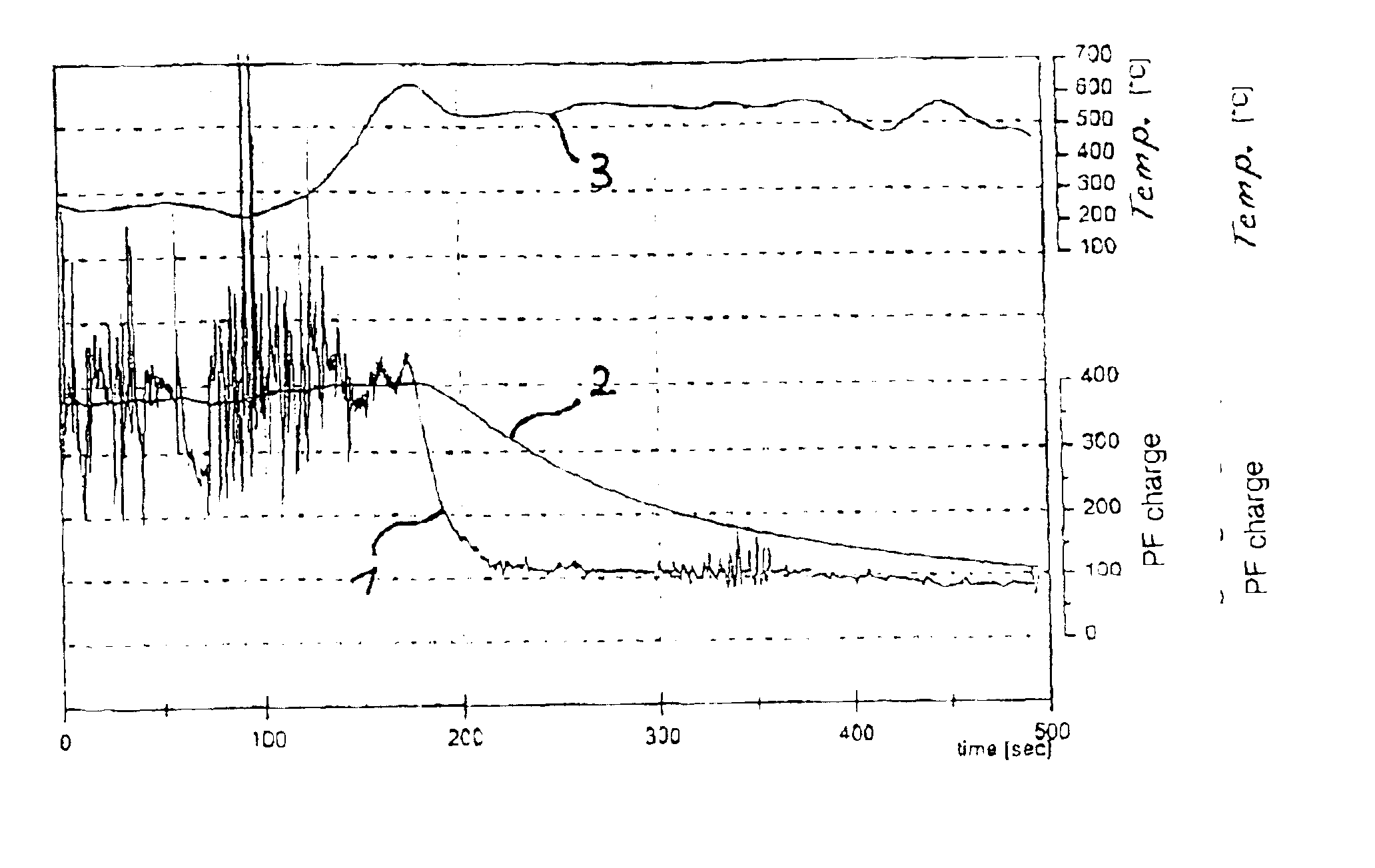
In a further refinement of the method according to the invention, in an operating state of the motor vehicle and / or of the internal combustion engine which is assigned to an active regeneration of the particle filter, the filtering operation is carried out when determining and / or processing the particle filter charge variable with a higher
cut-off frequency and / or smaller attenuation than in an operating state of the motor vehicle and / or of the internal combustion engine which is assigned to a charge of the particle filter. This measure improves the reliability of the evaluation of the pressure signal for the determination of the particle filter charge during the regeneration of the particle filter during which the charge of the particle filter decreases rapidly. When the particle filter regeneration and the associated operating state of the internal combustion engine are terminated, a slowly changing charge of the particle filter occurs again and the abovementioned measure is reversed, i.e. the cut-off frequency of the signal filtering operation is reduced again and / or the attenuation is increased again in operating states in which the particle filter is charged. In this way, the variable which is assigned to the charging of the particle filter is smoothed again to a greater extent, which ensures its reliable interpretation.

