Self-Centering Energy Dissipative Brace Apparatus With Tensioning Elements

a self-centering, energy dissipative technology, applied in the direction of building components, building types, constructions, etc., can solve the problems of increasing repair costs, economic unfeasibility, and energy dissipation per cycle through hysteretic yielding, and achieve efficient self-centering characteristics and minimize structural damage

Inactive Publication Date: 2008-01-24
POLYVALOR LP
View PDF37 Cites 57 Cited by
  • Summary
  • Abstract
  • Description
  • Claims
  • Application Information

AI Technical Summary

Benefits of technology

[0021] An object of the present invention is therefore to provide an apparatus which encompasses the same architectural features as current technology and the same response characteri

Problems solved by technology

It is economically unfeasible as well as being potentially unsafe to design structures for linear elastic response under such loading conditions, especially if, as a result of this design philosophy, no ductility capacity is provided in the system.
For yielding systems, the energy dissipated per cycle through hysteretic yielding (inelastic deformations) is generally associated with structural damage.
Such yielding systems are expected to sustain residual deformations which can greatly impair the structure and increase repair costs.
Structural damage and residual deformations are therefore expected under design level earthquakes.
They are expected to sustain significant damage after an earthquake due to repeated cycles of brace tension yielding and brace compression buckling.
Furthermore, as a direct consequence of the damage induced in these elements, the final state of the entire building is likely to be out of plumb.
Poor structural per

Method used


Image

  • Self-Centering Energy Dissipative Brace Apparatus With Tensioning Elements
  • Self-Centering Energy Dissipative Brace Apparatus With Tensioning Elements
  • Self-Centering Energy Dissipative Brace Apparatus With Tensioning Elements

Examples


second embodiment

[0126] A brace apparatus 130 according to the invention is illustrated in FIGS. 15 to 22. For concision purposes, only the differences between the brace apparatus 130 and the brace apparatus 30 illustrated in FIGS. 1 to 14j will be described hereinbelow. For simplification purposes, end connections (44a, 44d) will not be represented on FIGS. 15 to 22.

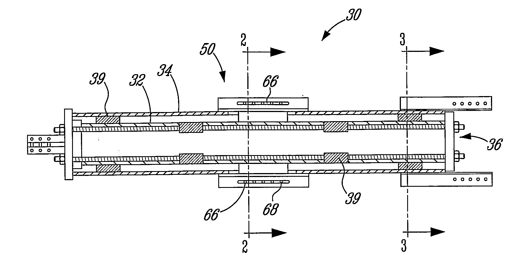
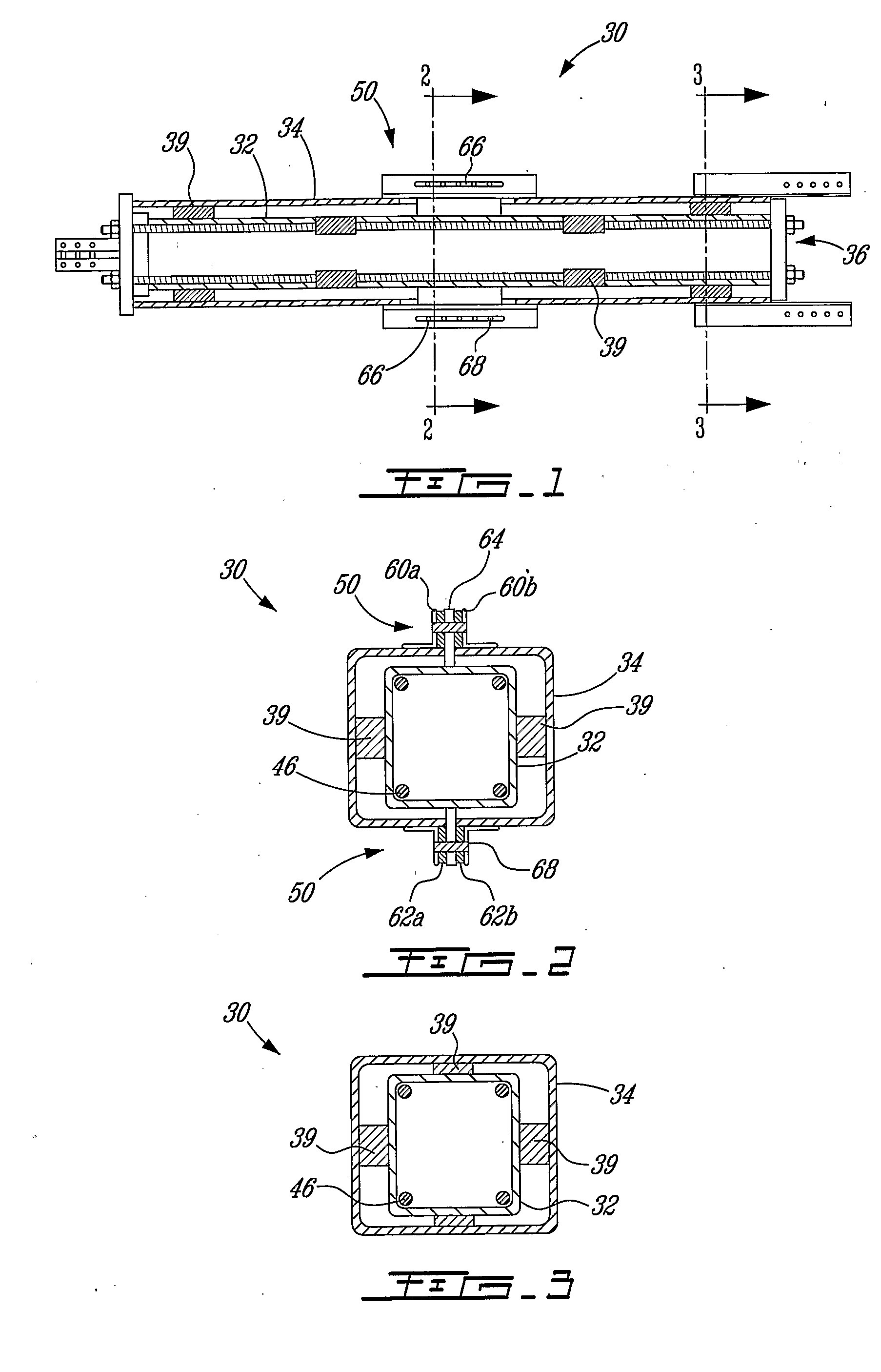
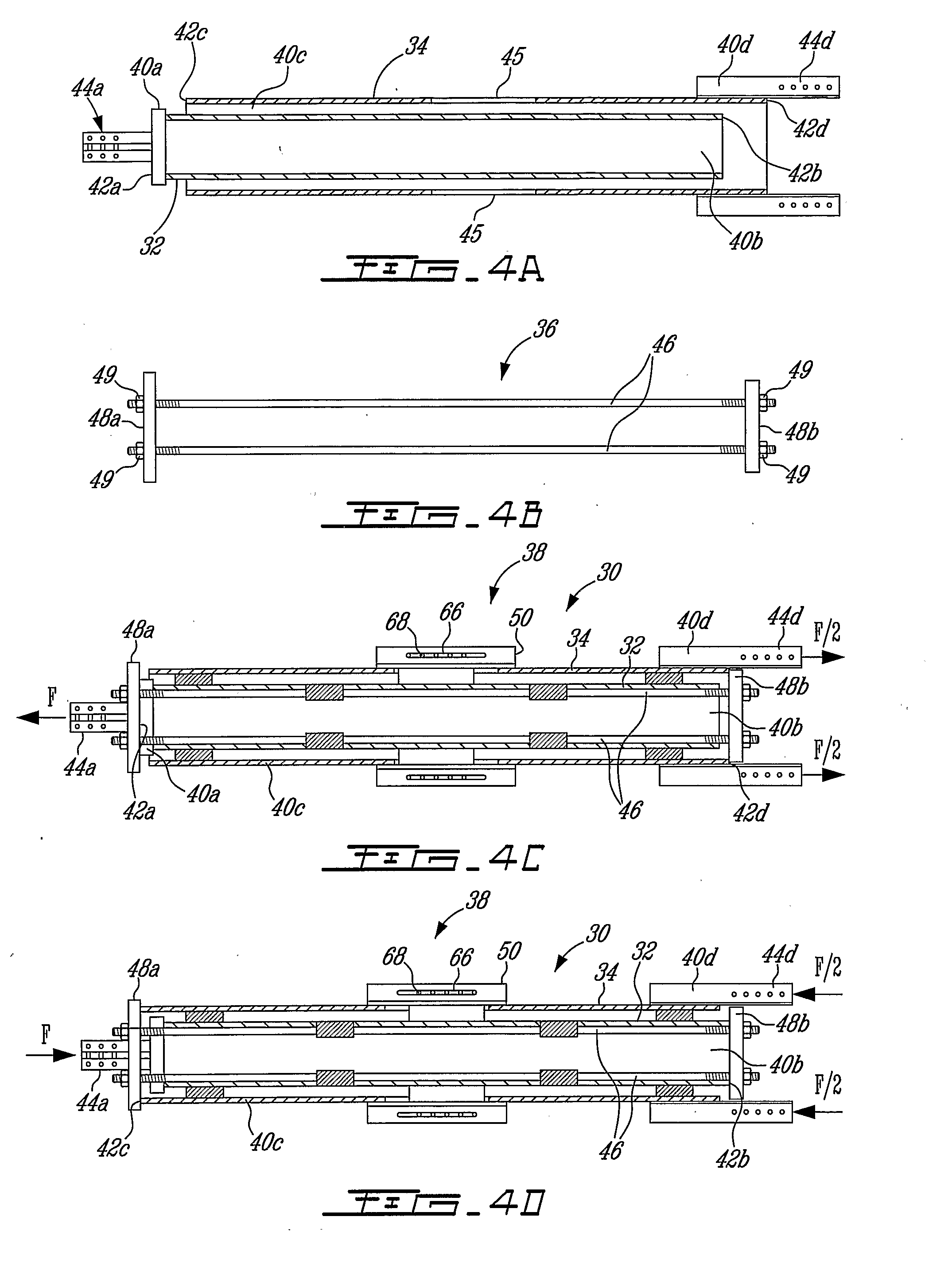
[0127] In this second illustrative embodiment, the brace apparatus 130 includes a first bracing member 132, a second bracing member 134, a tensionable assembly 136 and an energy dissipative system 138.

[0128] The energy dissipative system 138 includes two friction mechanisms 150a, 150b provided in proximity of the ends 140a, 140b, 140c, 140d. These friction mechanisms 150a, 150b each includes support members 160a, 160b, 160c, 160d mounted on the second bracing member 134 and extending members 164a, 164b mounted on the first bracing member 132. In this illustrative embodiment, the support members 160c, 160d and the extending member 164a ...

third embodiment

[0131] A brace apparatus 230 according to the invention is illustrated in FIG. 23. For concision purposes, only the differences between the brace apparatus 230 and the brace apparatus 30 illustrated in FIGS. 1 to 14j will be described hereinbelow.

[0132] In this illustrative embodiment, the brace apparatus 230 includes an inner bracing member 232, and two outer bracing members 234, 235 that are located on each side of the inner bracing member 232, a tensionable assembly 236, an energy dissipative system 238 and guiding elements 239.

[0133] The inner and outer bracing members 232, 234, 235 have ends 240a, 240b, 240c, 240d, 240e, 240f provided with respective abutting surfaces 242a, 242b, 242c, 242d, 242e, 242f. Ends 240a, 240d and 240f are further provided with end connections 244a, 244d, 244f, which in this embodiment include a threaded portion 245a, 245d, 245f.

[0134] The tensionable assembly 236 includes abutting elements 248a, 248b interconnected by tensioning elements 246. The ab...

first embodiment

[0137] The brace apparatus 230 operates in a similar way as described in the However, the loading force applied to the outer bracing members 234, 235 is half the force applied to the inner bracing member 232, but the effective apparatus 230 elongation is the same since two outer bracing members 234, 235 participate in elongating the apparatus 230.

[0138] A person skilled in the art will easily understand that the energy dissipative mechanism illustrated and described in this embodiment may be replaced by another hereinabove presented energy dissipative mechanism, such as, for example, a yielding, viscous, visco-elastic, or hysteritic mechanism.


PUM


Abstract

The present invention generally relates to a self-centering energy dissipative brace apparatus. A bracing system is often needed to stabilize, strengthen or stiffen structures such as buildings which are subjected to severe or extreme conditions. The brace apparatus may be installed in a structure to dissipate input energy and minimize residual deformations related to exceptional loading imposed on the structure by winds, earthquakes, impacts or explosions. The apparatus integrates self-centering properties and energy, dissipative capacities which help minimize structural damage.

Description

FIELD OF THE INVENTION [0001] The present invention generally relates to an energy dissipative brace apparatus with self-centering properties. More specifically, the present invention is concerned with a brace apparatus for installation in structures which may be subjected to extreme loading conditions. BACKGROUND OF THE INVENTION [0002] Although the design of structures under normal loading conditions aims at meeting serviceability and ultimate strength requirements by providing strength, stiffness and stability, it has been recognized recently that to effectively and safely resist extreme loading conditions such as earthquakes and blast loads, a fundamentally different approach must be used. It is economically unfeasible as well as being potentially unsafe to design structures for linear elastic response under such loading conditions, especially if, as a result of this design philosophy, no ductility capacity is provided in the system. This implies that the nonlinear behavior of y...

Claims


Application Information

Patent Timeline
IPC IPC(8): E04B1/98E04H9/00E04H9/02
CPCE04H9/028E04H9/02E04H9/0237E04B1/98E04H9/021
Inventor TREMBLAY, ROBERTCHRISTOPOULOS, CONSTANTIN
Owner POLYVALOR LP
Why Eureka
Try Eureka