Fuel supply system for DME engine

a technology of dme engine and supply system, which is applied in the direction of liquid fuel feeders, machines/engines, fuel injecting pumps, etc., can solve the problems of engine damage, abnormal combustion, and difficulty in preventing the evaporated dme in high pressure state from leaking ou

Inactive Publication Date: 2008-01-24
TOYOTA IND CORP
View PDF3 Cites 26 Cited by
  • Summary
  • Abstract
  • Description
  • Claims
  • Application Information

AI Technical Summary

Benefits of technology

[0007]An aspect in accordance with the present invention provides a fuel supply system using DME as fuel for a DME engine which comprises a fuel tank, a feed pump, a low-pressure fuel supply passage, a high-pressure supply pump, a high-pressure fuel supply passage, a fuel injector, a first fuel recovery passage, and a first solenoid valve. The fuel tank stores DME fuel as fuel for the DME engine. The feed pump rotates in a normal direction to supply the DME fuel in the fuel tank to the low-pressure fuel supply passage, and rotates in a reverse direction to recover the DME fuel to the fuel tank. The high-pressure supply pump is connected to the low-pressure fuel supply passage and the DME fuel is supplied to the high-pressure supply pump from the feed pump. The DME fuel is pressurized in the high-pressure supply pump and discharged therefrom. The high-pressure fuel supply passage distributes the DME fuel discharged from the high-pressure supply pump. The fuel injector injects the DME fuel distributed from the high-pressure fuel supply passage. The first fuel recovery passage connects the high-pressure fuel supply passage to the low-pressure fuel supply passage. The first solenoid valve opens and closes the first fuel recovery passage. When the engine is operated, the first solenoid valve closes the first fuel recovery passage. When the engine is stopped, the first solenoid valve opens the first fuel recovery passage and the feed pump rotates in a reverse direction, thereby the DME fuel in the low-pressure fuel supply passage and in the high-pressure fuel supply passage is recovered into the fuel tank.

Problems solved by technology

It is difficult to prevent the evaporated DME in high pressure state from leaking out.
When the engine is restarted, abnormal combustion may be happened and the engine may be damaged.
In the DME engine fuel supply system described above, large space is required to install the purge tank and the reliquefaction compressor, and such DME engine fuel supply system may not be provided on a small-sized truck.
Further, because materials which are applied to improve lubrication have corrosive properties against resin materials, resin materials are not able to use for member of the compressor.
That makes reduction in weight difficult.
Thus the system needs further larger space to install.
Because high compression rate is required for reliquefaction, high energy is required for driving reliquefaction compressor and that may cause energy loss in the whole system.

Method used


Image

  • Fuel supply system for DME engine
  • Fuel supply system for DME engine
  • Fuel supply system for DME engine

Examples


first embodiment

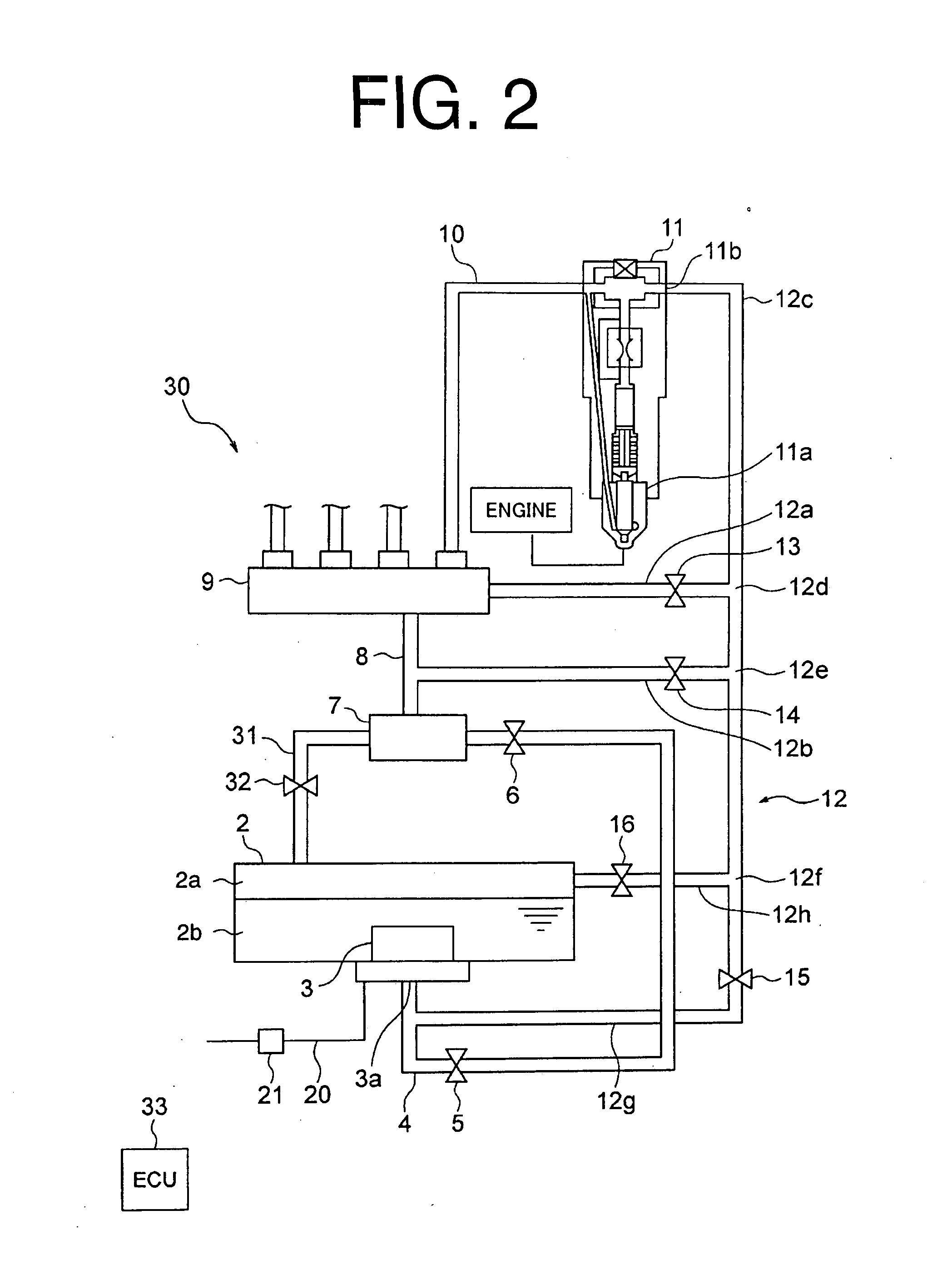
[0030]FIG. 2 shows a fuel supply system 30 for a DME engine. The gas phase part 2a of the fuel tank 2 is connected to the high-pressure side of high-pressure supply pump 7 through a third fuel recovery passage 31. The third fuel recovery passage 31 includes a fourth solenoid valve 32 to open and close the third fuel recovery passage 31. The fourth solenoid valve 32 is electrically connected to an ECU 33. The fourth solenoid valve 32 is controlled to be closed when the engine is operated, and to be opened when the engine is stopped. The ECU 33 controls not only the operation of the fourth solenoid valve 32, but also the operation of the solenoid valves 6, 13, 14, 15, 16 and switch 21, similar to the ECU 22 in the

[0031]The gas phase part 2a of the fuel tank 2 is connected to the high-pressure side of the high-pressure supply pump 7. Thus, the fuel supply system 30 equalizes the pressure of the DME fuel which is remained in high-pressure state at the downstream side of the high-pressur...

third embodiment

[0045]The operation of the fuel supply system 51 for the DME engine will be described with reference to FIG. 4 and the table 2. As indicated in the table 2, when the engine is operated, the feed pump 52 rotates in the normal direction, and the compression chamber is connected to the discharge port 52a through the solenoid switching valve 52c. When the engine is stopped, the feed pump 52 rotates in the reverse direction, and the feed pump 52 is connected to the discharge port 52a through the solenoid switching valve 52c. Thus, until when the predetermined time t has passed after the stop of the engine, the fuel supply system 51 is operated similar to the fuel supply system 41 of the Accordingly, the DME fuel does not flow into the flow supply passage 53 which is connected to the discharge port 52b, and DME is not supplied to the supply port 44a of the ejector 44.

[0046]When the predetermined time t has passed after the stop of the engine, the feed pump 3 rotates in the normal directi...


PUM


Abstract

A feed pump of a fuel supply system for a DME engine rotates in a normal direction to supply DME fuel in a fuel tank to a high-pressure supply pump through a low-pressure fuel supply passage. The high-pressure supply pump pressurizes the DME fuel and discharges the DME fuel therefrom. The discharged DME fuel is distributed by a high-pressure fuel supply passage and injected by a fuel injector. A first fuel recovery passage connects the high-pressure fuel supply passage to the low-pressure fuel supply passage. When the engine is operated, a first solenoid valve closes the first fuel recovery passage. When the engine is stopped, the first solenoid valve opens the first fuel recovery passage and the feed pump rotates in a reverse direction, thereby the DME fuel in the low-pressure fuel supply passage and in the high-pressure fuel supply passage is recovered into the fuel tank.

Description

BACKGROUND OF THE INVENTION[0001]The present invention relates to a fuel supply system for a DME engine which uses DME (dimethylether) as fuel for an engine, and which recovers fuel when an engine is stopped.[0002]DME is a clean energy which does not have serious influence on environment, and in recent years it has been attracting attention as a fuel in the next-generation. Especially DME has high cetane number and is oxygenated fuel, thereby emissions of black smoke is low when the DME fuel is combusted. Further, by exhaust gas recirculation (EGR), DME reduces the emission of NOx (nitrogen oxides) and particulate matter (PM). Thus, DME is expected to be utilized practically as an alternative fuel for light oil in a diesel engine.[0003]DME has very low boiling point (minus 25 degrees centigrade), and easily evaporates. When the engine is stopped, highly-pressurized DME which is remained in a fuel supply passage of a DME fuel supply system is evaporated by heat from the engine and it...

Claims


Application Information

Patent Timeline
Patent Type & Authority Applications(United States)
IPC IPC(8): F02M61/16
CPCF02M37/0076F02M21/00
Inventor MOROI, TAKAHIROSUZUKI, SHIGERUOTA, MASAKI
Owner TOYOTA IND CORP
Why Eureka
Try Eureka