Permanent magnet type electric rotary machine and compressor using the same

a permanent magnet and electric rotary machine technology, applied in the direction of dynamo-electric machines, magnetic circuit rotating parts, magnetic circuit shape/form/construction, etc., can solve the problems of increasing vibration and grating noise, and increasing the noise of the motor itself, so as to achieve low vibration and noise. , the effect of low nois

Inactive Publication Date: 2008-01-24
HITACHI IND EQUIP SYST CO LTD
View PDF13 Cites 76 Cited by
  • Summary
  • Abstract
  • Description
  • Claims
  • Application Information

AI Technical Summary

Benefits of technology

[0012] An object of the present invention is to provide a permanent magnet type electric rotary machine low in vibration as well as noise without causing deterioration in performance such as motor efficiency and so forth, and a compressor using the same.

Problems solved by technology

As a consequence, it brings an increase in vibration and noise of the motor itself, and an intermediate frequency band noise, which is a most grating noise, increases markedly in the case of the motor being particularly assembled into a compressor.
However, they are not effective sufficiently to reduce the noise in the intermediate frequency band that is a problem picked up herein.
The reason for this is that, in the case of the technology according to the Patent Document 1, in order to cancel out a harmonic component of a low order being longer in wavelength, it needs to adopt a large skew pitch structure, resulting in deterioration of characteristics.
However, if an attempt is made to cope with harmonic components of a high order by increasing the number of the slits, this will cause an increase in magnetic resistance of the rotor, resulting in deterioration of the characteristics.
For this reason, there are limitations to the number of the slits that can be disposed in a rotor core, so that this method will be effective only for harmonic components of a low order.

Method used


Image

  • Permanent magnet type electric rotary machine and compressor using the same
  • Permanent magnet type electric rotary machine and compressor using the same
  • Permanent magnet type electric rotary machine and compressor using the same

Examples


embodiment 2

[0053] FIGS. 5(a) and 5(b) are partial magnified cross-sectional views showing a shape of a rotor core 12 of a permanent magnet type electric rotary machine of the present invention. In detail of them, FIG. 5(a) is a partial magnified cross-sectional view of a B-part of the rotor core 12 corresponding to FIG. 4, and FIG. 5(b) is a partial magnified cross-sectional view of an A-part of the rotor core 12 corresponding to FIG. 4. Parts identical to those in FIGS. 1 to 4, respectively, are denoted by like reference numerals. The shape of the rotor core, in FIGS. 5 (a) and 5(b), partially differs from those shown in FIGS. 1 to 4, respectively, in that respective intervals A, B, and C between adjacent slits 10 (10a to 10d) are set by irregular pitches. With adoption of such a configuration, it becomes possible to make finer adjustment of magnetic flux distribution by making adjustments of magnetic skew angles in respective parts A and B.

embodiment 3

[0054] FIGS. 6(a) and 6(b) are partial magnified cross-sectional view showing a shape of a rotor core 12 of a permanent magnet type electric rotary machine of the present invention. In detail of them, FIG. 6(a) is a partial magnified cross-sectional view of a B-part of the rotor core 12 corresponding to FIG. 4, and FIG. 6(b) is a partial magnified cross-sectional view of an A-part of the rotor core 12 corresponding to FIG. 4. Parts identical to those in FIG. 5 are denoted by like reference numerals. The shape of the rotor core, in FIGS. 6 (a) and (b), partially differs from that shown in FIG. 5 in that slits 10 formed such that one half-side with respect to the d-axis is provided with a length of slit 10d (B part of FIG. 6(a)) or slit 10c (A part of FIG. 6(b)), and another half-side with respect to the d-axis is provided with two length of slits 10a, 10c (B part of FIG. 6 (a)) or slits 10b, 10d (A part of FIG. 6 (b)). With adoption of such a configuration of the arrangement that di...

embodiment 4

[0055]FIG. 7(a) is a perspective view showing a shape of a rotor core 12 of a permanent magnet type electricrotary machine of the present invention. FIG. 7(b) is a front view showing a shape of a rotor core 12 thereof. Parts identical to those in FIG. 4 are denoted by like reference numerals. The shape of the rotor core, in FIG. 7, partially differs from that shown in FIG. 4 in that: the rotor core 12 is comprised of a multilayered structure of three A-part blocks and two B-part blocks alternately being layered to each other, so that concave portions 40 like stepped w-shape (in other words, stepped zigzag line) in the circumferential direction on the outer surface of the rotor core 12.

[0056] Even according to such a configuration, it is possible to suppress an axial thrust. Further, since it is possible to make an increase in magnetic coupling between adjacent parts A and B in the axial direction, apparent skew pitches can be rendered smaller, so that skew pitches can be suitably a...


PUM


Abstract

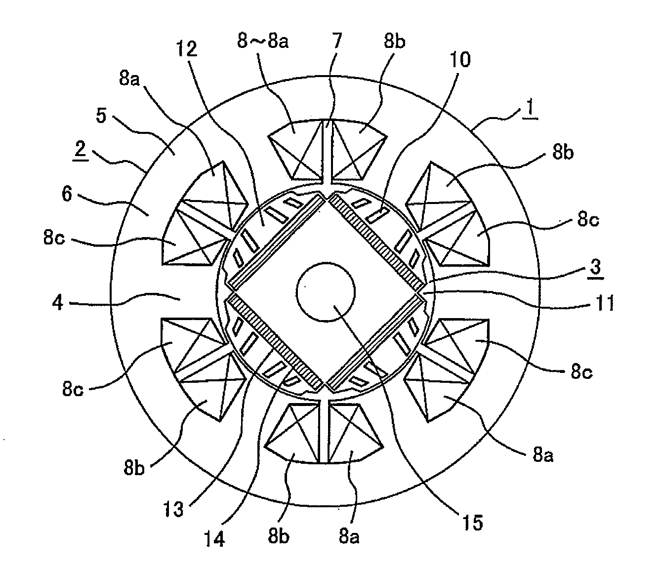
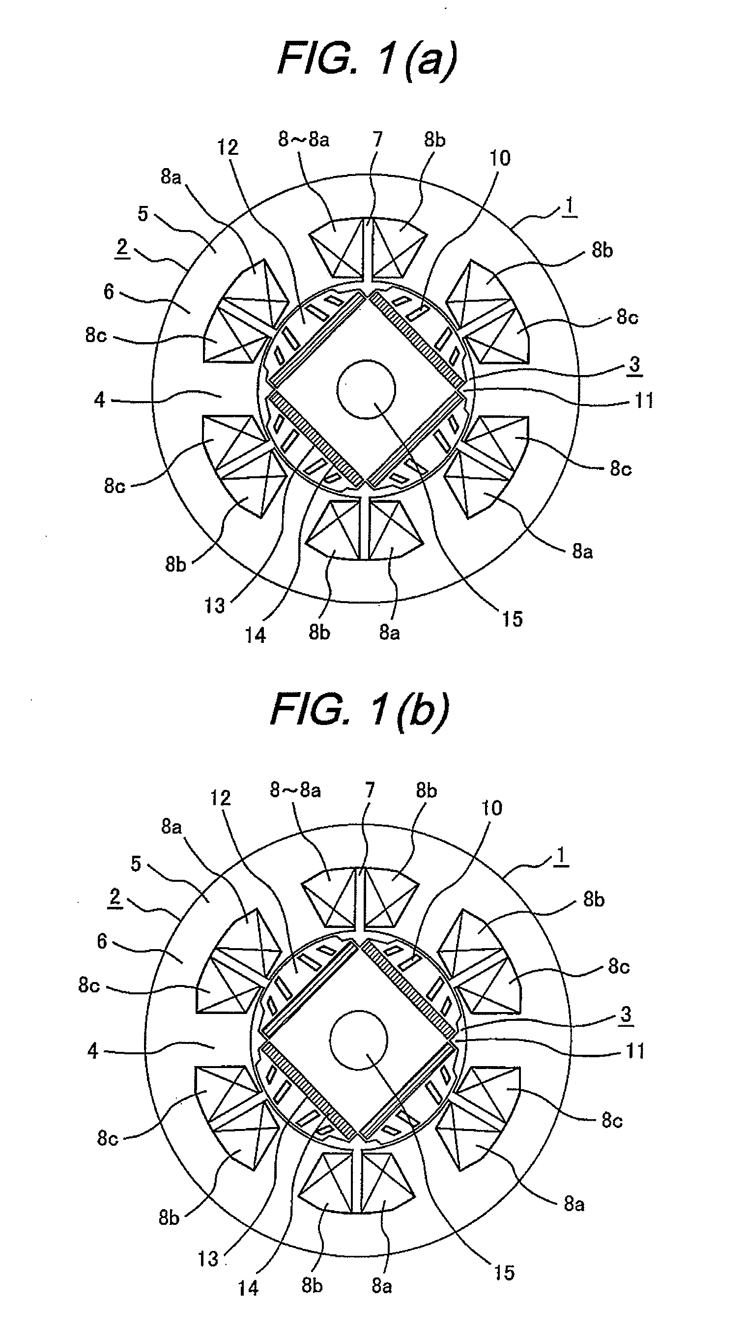
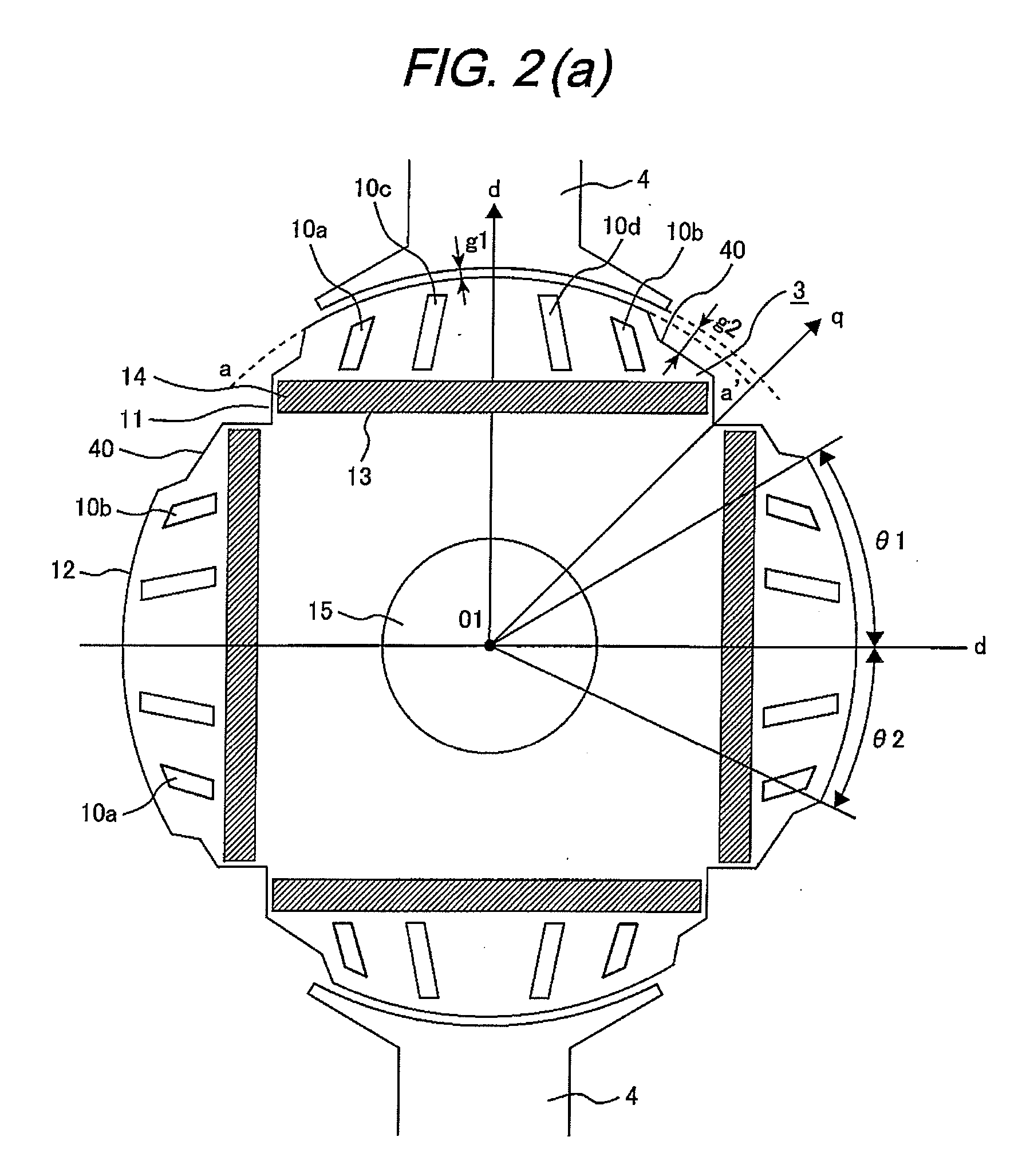
A permanent magnet type electric rotary machine includes a stator including a stator core having teeth and slots, and a rotor provided with permanent magnets as magnet poles in a rotor core. A pole core portion which between each of the permanent magnets and an outer surface of the rotor core is provided with a plurality of pole slits. A region of the pole core portion is defined by concave portions provided on q-axes to be interpolars on both sides of the pole core portion, and thereby configured that a gap between the outer surface on the q-axis of the rotor core and an inner surface of the stator core is larger than a gap between the outer surface on the d-axis of the pole core portion and the inner surface of the stator, so that magnetic fluxes from the permanent magnet pass through the pole core portion concentrately.

Description

CLAIM OF PRIORITY [0001] The present application claims priority from Japanese application serial no. 2006-197562, filed on Jul. 20, 2006, the content of which is hereby incorporated by reference into this application. TECHNICAL FIELD [0002] The present invention relates to a permanent magnet type electricrotary machine including a rotor provided with a permanent magnet for a field magnet, and in particular, to a permanent magnet type electric rotary machine to be used in a compressor for an air conditioner, a refrigerator, a freezer, or a showcase. BACKGROUND OF THE INVENTION [0003] In this kind of permanent magnet type electricrotary machine, a concentrated winding has been used for a stator winding, and a rare-earth neodymium permanent magnet have been used for a field magnet, thereby having achieved higher efficiency of the rotary machine. Incidentally, vibration and noise components of an electric rotary machine have become larger as a magnetic material has gotten higher streng...

Claims


Application Information

Patent Timeline
Patent Type & Authority Applications(United States)
IPC IPC(8): H02K1/27H02K1/12
CPCH02K1/2766H02K1/276
Inventor TAKAHATA, RYOICHIKIKUCHI, SATOSHIWAKUI, SHINICHINOMA, KEIJISENOO, MASAHARU
Owner HITACHI IND EQUIP SYST CO LTD
Why Eureka
Try Eureka