Supercharge Your Innovation With Domain-Expert AI Agents!

Plasma display panel and production process of same

a technology of display panel and plasma, which is applied in the manufacture of electric discharge tube/lamp, discharge tube luminescnet screen, electrode system, etc., can solve the problems of reducing the lifetime of the panel, unable to completely avoid, and sustaining the discharge between the display electrode, so as to achieve the effect of prolonging the lifetime of the phosphor

Inactive Publication Date: 2008-01-24
FUJITSU HITACHI PLASMA DISPLAY LTD
View PDF1 Cites 0 Cited by
  • Summary
  • Abstract
  • Description
  • Claims
  • Application Information

AI Technical Summary

Benefits of technology

[0007]Moreover, although the vehicle in the phosphor paste is removed by heat treatment, since it cannot always be completely removed, a trace amount of organic matter remains in the phosphors. Since this organic matter causes phosphor deterioration, brightness is attempted to be stabilized by carrying out an aging step consisting of continuous discharge after the front substrate and back substrate have been sealed to form a panel. However, this aging step leads to increased production costs.
[0008]Therefore, an object of the present invention is to provide a plasma display panel, and a production process thereof, capable of eliminating phosphor deterioration caused by ion bombardment and avoiding increases in costs attributable to an aging step.
[0010]According to this first aspect, since the phosphors are separated from a discharge space by the second substrate, the lifetime of the phosphors can be extended as a result of not being subjected to ion bombardment.
[0012]According to a preferable mode of this second aspect, a secondary ion emission layer is formed on the lateral surface of the barrier. As a result thereof, the effective discharge voltage can be lowered and emission efficiency can be improved. In addition, according to a different preferable mode, light emitted by the phosphors can be effectively guided to the front side by forming the phosphors on a reflective layer.
[0014]According to this third aspect, an aging step can be eliminated by filling phosphor powders into recesses formed in the third substrate or recesses formed in the second substrate.
[0015]According to the present invention, phosphor lifetime can be extended without causing deterioration thereof attributable to ion bombardment.

Problems solved by technology

Although a three-electrode surface discharge type of panel of the prior art is resistant to ion bombardment during plasma discharge by providing the phosphors on a back substrate, since phosphors are still present in the discharge space, damage caused by ion bombardment accompanying address discharge occurring between the display electrodes the address electrodes, and sustain discharge occurring between display electrodes, cannot be completely avoided.
This ion bombardment invites deterioration of the phosphors and causes a reduction in panel lifetime.
Moreover, although the vehicle in the phosphor paste is removed by heat treatment, since it cannot always be completely removed, a trace amount of organic matter remains in the phosphors.
However, this aging step leads to increased production costs.

Method used


Image

  • Plasma display panel and production process of same
  • Plasma display panel and production process of same
  • Plasma display panel and production process of same

Examples


Embodiment Construction

[0028]The following provides an explanation of embodiments of the present invention with reference to the drawings. However, the technical scope of the present invention is not limited to these embodiments, but rather extends to the matters described in the scope of claim for patent and matters equivalent thereto.

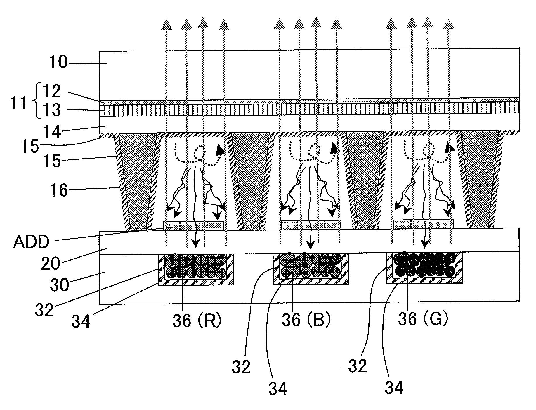
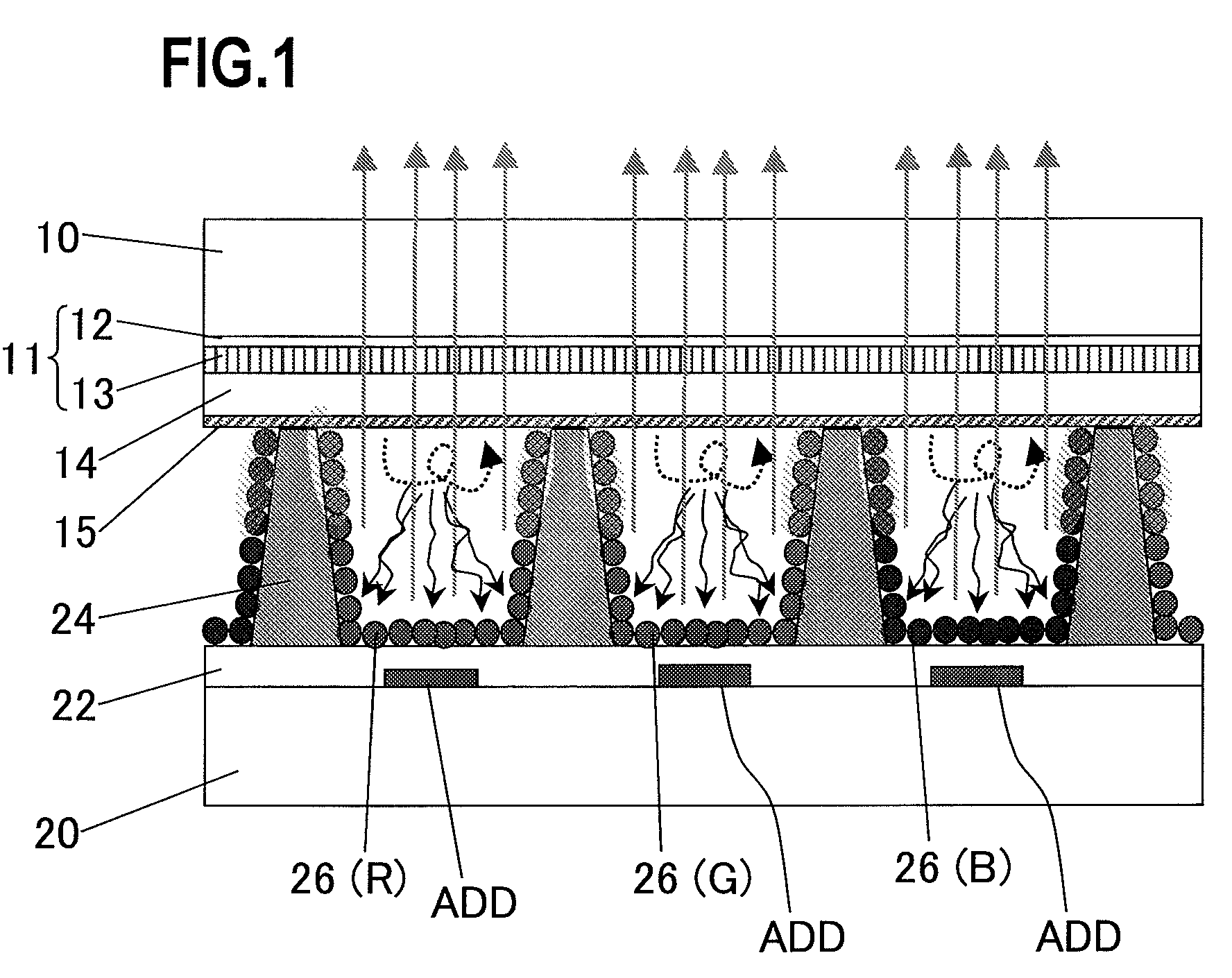
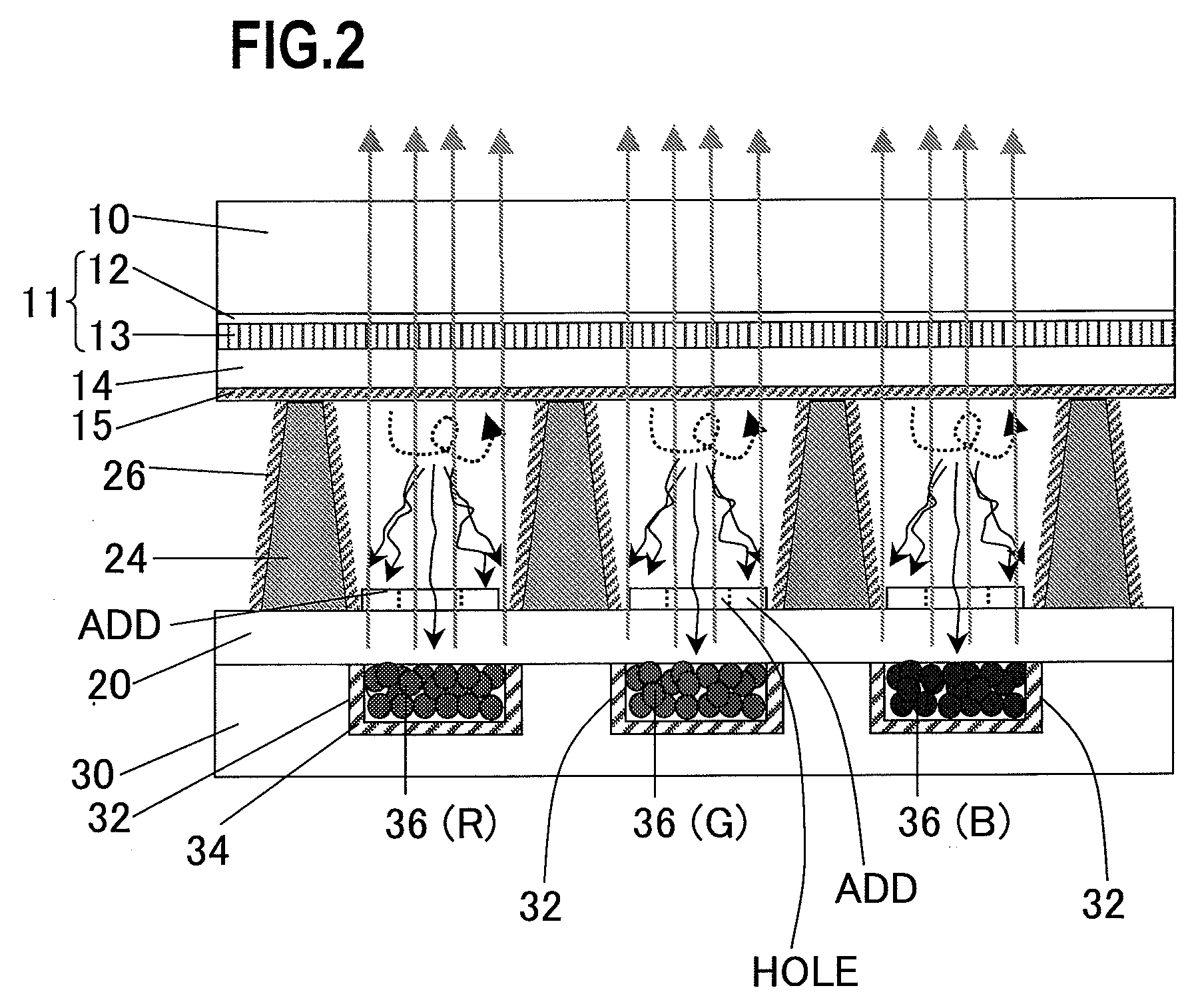
[0029]FIG. 1 is a cross-sectional view of a three-electrode surface discharge type of plasma display panel of the prior art. Display electrodes 11, comprised of a transparent electrode 12 and a bus electrode 13 of a highly conductive metal (three-layer structure of Cr / Cu / Cr) superimposed thereon, a dielectric layer 14 covering the display electrodes 11, and a protective layer 15 comprised of MgO covering the dielectric layer 14, are formed on a side of a discharge space of a front side glass substrate 10.

[0030]On the other hand, address electrodes ADD, which intersect with the display electrodes 11 and form unit emission regions at the locations of those intersections, a di...


PUM


Abstract

To extend phosphor lifetime and lower the production cost of forming the phosphors.A plurality of display electrodes 11, a dielectric layer 14 which covers the display electrodes 11, and a protective layer 15 which covers the dielectric layer 14 are formed on a front side first substrate 10, a plurality of address electrodes ADD, which intersect the display electrodes and form unit emission regions at the intersections, are formed on the second substrate 20, and a third electrode 30 is adhered on the second substrate with phosphors 36 interposed therebetween; and the first and the second substrates are sealed with a barrier 24 which demarcates the unit emission regions interposed therebetween. Since the phosphors 36 are separated from a discharge space by the second substrate 20, deterioration thereof caused by ion bombardment is prevented.

Description

BACKGROUND OF THE INVENTION[0001]The present invention relates to a plasma display panel and a production process thereof, and more particularly, to a novel structure of a plasma display panel, which improves the lifetime of phosphors and eliminates deterioration of characteristics, and a production process thereof.[0002]Plasma display panels have become popular in recent years. These plasma display panels employ a three-electrode surface discharge structure. Display electrodes extending in the horizontal direction, a dielectric layer covering the display electrodes, and a protective layer protecting the dielectric layer, are formed on a front substrate, while address electrodes intersecting with the display electrodes, a striped or matrix-like barrier, which demarcates unit emission regions where the display electrodes and the address electrodes intersect, and phosphors, provided on the address electrodes and side walls of the barrier, are formed on a back substrate.[0003]In this t...

Claims


Application Information

Patent Timeline
IPC IPC(8): H01J17/49H01J1/62H01J9/00H01J9/02H01J9/227H01J11/12H01J11/22H01J11/24H01J11/26H01J11/32H01J11/34H01J11/36H01J11/38H01J11/40H01J11/42
CPCH01J11/12H01J11/42H01J11/40H01J11/34H01J11/22
Inventor KANAE, TATSUTOSHIYAMANAKA, HIROSHI
Owner FUJITSU HITACHI PLASMA DISPLAY LTD
Features
  • R&D
  • Intellectual Property
  • Life Sciences
  • Materials
  • Tech Scout
  • Unparalleled Data Quality
  • Higher Quality Content
  • 60% Fewer Hallucinations
Learn More