Printing Apparatus, Ink Mist Collecting Method, and Printing Method

a printing apparatus and ink mist technology, applied in the field of printing apparatus, can solve the problems of difficult to accurately attach all droplets to desired printing positions, difficult to control ink droplets in such a small volume one by one, and difficult to obtain the desired precision under the influence of peripheral air flow, so as to achieve efficient attraction and collection, reduce the amount of ink mist which floats and attaches to unintended portions of the apparatus, and high-quality printing

Inactive Publication Date: 2008-01-24
CANON KK
View PDF26 Cites 32 Cited by
  • Summary
  • Abstract
  • Description
  • Claims
  • Application Information

AI Technical Summary

Benefits of technology

[0021] For example, a printing apparatus, ink mist collecting method, and printing method according to the present invention are capable of controlling the traveling direction of fine ink droplets by electrostatic force, collecting unwanted floating ink droplets (ink mist) or attaching ink mist onto desired positions on a printing medium, and thereby achieving high-quality printing.
[0033] The invention is particularly advantageous since charged ink mist which is generated upon discharge of ink droplets is efficiently attracted and collected by electrostatic force, and the amount of ink mist which floats and attaches to unintended portions in the apparatus decreases.
[0034] Hence, the present invention can prevent: (1) contamination of the interior of the printing apparatus by attached ink mist; (2) degradation of the movable characteristic by ink mist which attaches to the movable portion of the printing apparatus, e.g., the movable portion of the carriage; (3) a malfunction of a sensor by ink mist which attaches to the sensor; (4) contamination of the exterior of the apparatus by aggregated ink which leaks from the printing apparatus; and (5) contamination of the next printing medium by attached ink mist.
[0035] According to another invention, the surface of a printing medium is so charged as to have a polarity opposite to that of charged satellite ink which is separated from an ink droplet discharged from the printhead for printing. Satellite ink can be attracted to the printing medium and used for printing. Thus, satellite ink can be actively used for printing. Since satellite ink does not float to contaminate a printing medium, high-quality printing can be achieved.

Problems solved by technology

An ink droplet 1.0 pl in volume is regarded as mist, and it becomes difficult to control ink droplets in such a small volume one by one.
However, it is difficult to obtain the desired precision under the influence of a peripheral air flow.
For this reason, it is difficult to accurately attach all droplets to desired printing positions.
If the above-mentioned satellites or ink droplets bounded back from the surface of a printing medium float in the air to accumulate fine ink droplets, such fine ink droplets contaminate the interior of the printing apparatus and / or degrade the movable characteristic of the movable portion of the printing apparatus.
In addition, the fine ink droplets cause various sensors to malfunction.
Further, aggregated floating mist during printing attaches to the upper and lower surfaces of a printing medium, or mist left in the apparatus attaches to the upper and lower surfaces of the next printing medium subjected to printing, thereby contaminating the printing medium.
The techniques disclosed in these prior arts have the following problems.
It is practically difficult to perform such control, or high-speed printing is limited.
Electromagnetic waves are generated by high-frequency control of the electric field and act as a noise source, degrading the reliability and safety of the printing apparatus.
It is difficult to control a fine droplet.
It is, therefore, difficult to accurately control a satellite droplet.
In the method according to Japanese Patent Publication Laid-Open No. 2002-211005, the structure of the printing apparatus becomes complicated because a charging mechanism for each type of ink must be arranged.
The method according to Japanese Patent Publication Laid-Open No. 2003-014773 does not intend to force ink droplets to move toward a printing medium, and poses a problem in achieving high-quality printing.

Method used


Image

  • Printing Apparatus, Ink Mist Collecting Method, and Printing Method
  • Printing Apparatus, Ink Mist Collecting Method, and Printing Method
  • Printing Apparatus, Ink Mist Collecting Method, and Printing Method

Examples


first embodiment

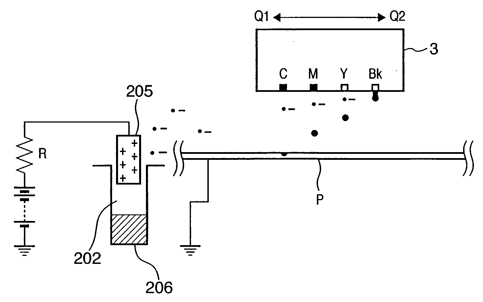
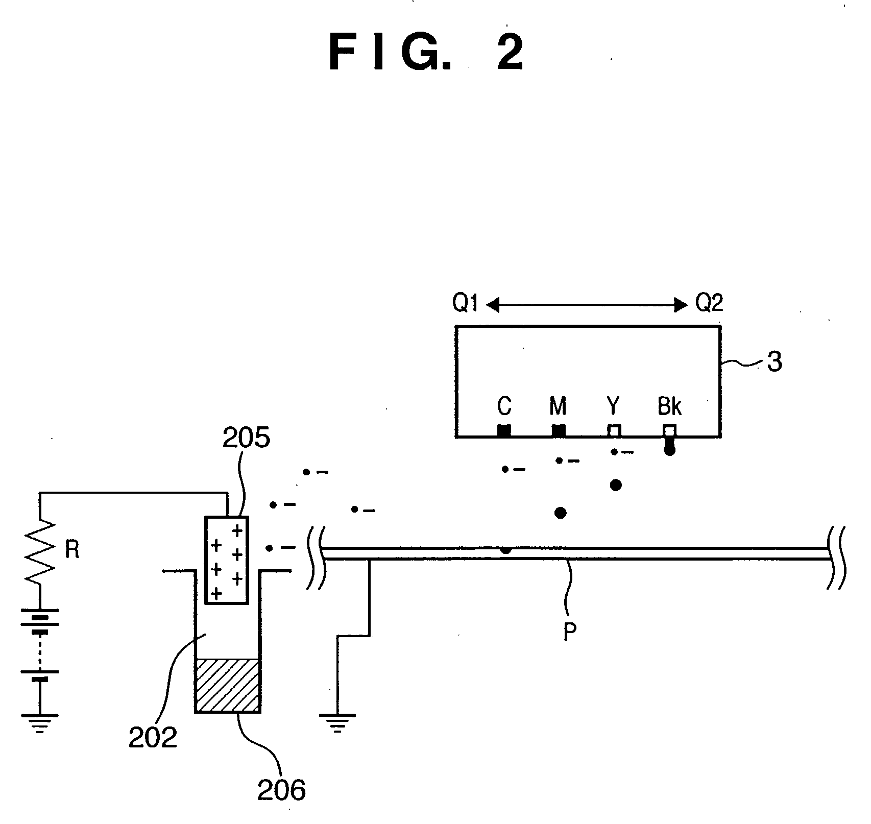
[0087] Most of ink droplets about 5 pl (picoliter) in volume discharged from a printhead 3 attach to a printing medium P and form an image. However, small satellites generated around the tail ends of ink droplets, and fine ink droplets bounded back from the printing medium P float in the apparatus. If such satellites and fine ink droplets are left to stand, they contaminate unlimited portions in the apparatus. Especially, satellites and fine ink droplets tend to deposit at electrostatically charged portions such as a sliding portion (e.g., guide shaft 13). There is known a phenomenon (Lenard effect) in which droplets tend to be charged either positively or negatively, especially negatively when an internally polarized droplet is broken into particles or droplets collide against each other in a process of forming (spraying) small droplets containing water.

[0088] For this reason, fine ink droplets (e.g., satellites) generated when ink droplets are discharged from the printhead 3 tend...

second embodiment

[0100] For example, in a large-scale printing apparatus for commercial use or the like that prints on a printing medium as large as A0 or B0, it is difficult to efficiently collect ink mist in the entire apparatus by the ink mist collecting method which only depends on spontaneous diffusion of ink mist and electrostatic force, as described in the first embodiment, because the distance to the ink mist collecting unit is long.

[0101] Taking this into consideration, the second embodiment will explain a configuration in which ink mist floating in the apparatus is forcedly moved by an air current toward the ink mist collecting unit.

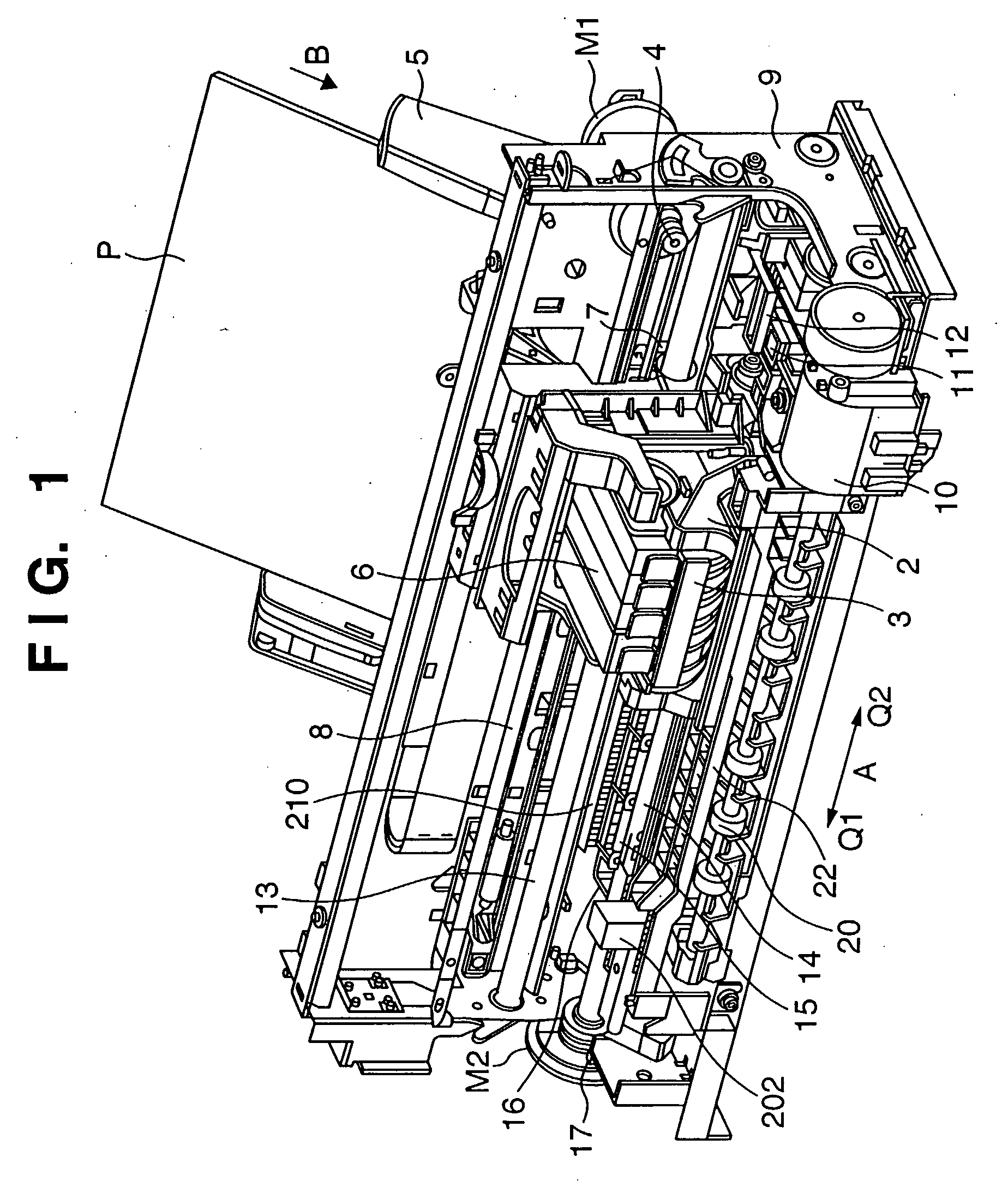
[0102]FIG. 7 is an outer perspective view showing the schematic configuration of a printing apparatus according to the second embodiment. As is apparent from a comparison between FIGS. 7 and 1, their configurations are almost the same. The same reference numerals denote the same parts, and a description thereof will be omitted.

[0103] A characteristic feature...

third embodiment

[0109] Ink droplets discharged from the printhead generally travel straight and attach to a printing medium. However, if the printhead moves at a high speed, ink droplets may attach to unintended positions because of an air flow generated by the movement of the printhead or an air flow generated by ink droplets themselves which are successively discharged from the printhead. To solve this problem, a method of increasing the initial velocity of ink droplets to suppress the influence of the air resistance and air flow and increase the precision of attaching positions on a printing medium has conventionally been employed.

[0110] However, as schematically shown in a of FIG. 5 in connection with the first embodiment, ink mist (satellites) which is a problem in the present invention is generated by a phenomenon in which the shape of an ink droplet is deformed into a teardrop shape, and a tail part of the droplet is torn off upon ink discharge. It is, therefore, difficult to increase the i...


PUM

PropertyMeasurementUnit
volumeaaaaaaaaaa
volumeaaaaaaaaaa
volumeaaaaaaaaaa

Abstract

There are provided a printing apparatus and printing method capable of collecting unwanted ink mist and achieving high-quality printing by fine ink droplets. According to the method, the charges of a printing medium are removed prior to printing, and an ink mist collecting unit having an electrode of a positive polarity is employed. Floating ink mist is collected such that ink mist generated from discharged ink droplets and negatively charged is moved toward the ink mist collecting unit by the electrostatic force.

Description

TECHNICAL FIELD [0001] This invention relates to a printing apparatus, ink mist collecting method, and printing method, and more particularly to a printing apparatus, ink mist collecting method, and printing method using an inkjet printhead which prints by, e.g., discharging fine ink droplets onto a printing medium. BACKGROUND ART [0002] An inkjet printing apparatus forms an image by fixing small ink droplets serving as a coloring material onto the surface of a printing medium. Recently, printing is done on a printing medium by using not only four conventional color inks including cyan (C), magenta (M), and yellow (Y) color inks and black (Bk) ink, but also low-density inks of similar colors (e.g., light magenta and light cyan), and orange, blue, green, and skin color inks. [0003] The volume of one ink droplet used in the inkjet printing apparatus decreases to 1.0 pl (picoliter) in order to meet recent demands for higher image quality. [0004] An ink droplet 1.0 pl in volume is regar...

Claims


Application Information

Patent Timeline
Patent Type & Authority Applications(United States)
IPC IPC(8): B41J2/04
CPCB41J2/185B65H2301/5133B41J11/0015B41J2/20B41J2/1714
Inventor MASUYAMA, ATSUHIKOMORIYAMA, JIRO
Owner CANON KK
Why Eureka
Try Eureka