Visual effect apparatus for displaying interlaced images using block out grids

a visual effect and grid technology, applied in the field of optical illusions and devices, can solve the problems of not being decals or other, and the thickness of the substrate is not generally useful or desirable for labels or other purposes, and achieve the effects of effective viewing interlaced images, facilitating focusing a powerful lens, and increasing the shelf appeal of products

Inactive Publication Date: 2008-01-24
GENIE LENS TECH
View PDF23 Cites 13 Cited by
  • Summary
  • Abstract
  • Description
  • Claims
  • Application Information

AI Technical Summary

Benefits of technology

[0011] In prior block out grids, a block out grid is printed or attached to one side of a substrate of transparent material (such as glass or plastic or the like) with the interlaced image being attached to the other or reverse side of the substrate. To achieve desirable results, the substrate had to be relatively thick, such as 0.125 inches or more thick, and, as a result, block out grids have typically been limited in use to flat displays where the rigidity of the substrate is acceptable. However, such a thick substrate is not generally useful or desirable for a label or decal or other packaging for consumer products. To address this need, the present invention provides a number of embodiments in which a block out grid can be provided on a container sidewall, as part of a container sidewall, on or as part of a label or other packaging to view an interlaced image. As will become apparent, the block out grid may be used in the place of a lenticular lens array to effectively view interlaced images and achieve desirable optical effects that increase shelf appeal of products.
[0012] In one embodiment, the present invention addresses the above problems by providing a lenticular lens systems with a lenticular lens array or block out grid fabricated as part of the container to be integral with one of the container walls. In other words, the container itself is used to construct a lenticular lens array or block out grid to focus on a selected portion of the container in which a printed image is positioned. In one embodiment, the lenticular lens array is integrally formed in a front portion of a clear container wall to focus on a rear portion of the container wall with the lenticules on an exterior surface of the container. In another embodiment, the lenticular lens array is replaced with a block out grid that is provided proximate to the front portion of the clear wall container to focus on the rear portion of the container wall. The block out grid may be formed integrally with the container wall, printed onto the interior or exterior surface of the front portion of the container wall, attached to or near the exterior or interior surface of the front portion of the container wall. A label or other image presentation element is attached to the container so as to precisely position a printed image adjacent the rear portion of the container upon which the lenticular lens assembly is focusing. The lenticular lens assembly or block out grid can be configured to produce a graphical image from the printed image at a number of locations within the container or, in some cases, outside the container. In one embodiment, the graphical image is displayed so as to appear to be floating within liquid contents of the container, such as water or other clear or translucent liquid, in the center of the container. The space or distance in the container between the lens array (or block out grid) and the rear portion of the container is selected to facilitate focusing a powerful lens on the rear portion to enable a wider or more coarse lens array (or block grid) that has space to carry more data and / or more images, which creates a greater overall visual effect.
[0013] In other embodiments, the present invention addresses the above problems by providing packaged containers (or packaging systems) in which a focusing gap (or “air gap”) is provided between a lenticular lens array or block out grid and a corresponding interlaced image. The focusing gap is useful for allowing the focal length to be significantly larger without large increases in lens thicknesses, which is desirable to allow standard packaging processes, such as attaching of wrap around labels, to be used to apply the lenticular lens arrays or block out grids. For example, some embodiments of the invention include a container with a recessed surface in its side wall. A wrap around label is then attached to the side wall of the container to produce enhanced graphics. The wrap around label includes an image portion or element that is attached to the container within the recessed surface. The label further includes a lens portion or element that includes a lenticular lens array (or set of lenses) or a block out grid. The lens element or portion of the label is then applied to the side wall of the container so as to extend over the recessed surface and the previously positioned image element. In this manner, a gap filled with air (or other fluids) is formed between the lenses or block out grid and the printed image such that focusing can be effectively achieved through the material and thickness of the lens element and air and size of the focusing gap. As a result, much coarser lens arrays can be used with very thin labeling materials to achieve high quality graphics, e.g., 20 to 70 LPI (or coarser) lens arrays can be provided in 3 to 5 mil or thinner plastic sheets to achieve good imagery with an air gap of 0.5 inches or less (and often less than 3 / 16 inch gap is utilized).

Problems solved by technology

To achieve desirable results, the substrate had to be relatively thick, such as 0.125 inches or more thick, and, as a result, block out grids have typically been limited in use to flat displays where the rigidity of the substrate is acceptable.
However, such a thick substrate is not generally useful or desirable for a label or decal or other packaging for consumer products.

Method used


Image

  • Visual effect apparatus for displaying interlaced images using block out grids
  • Visual effect apparatus for displaying interlaced images using block out grids
  • Visual effect apparatus for displaying interlaced images using block out grids

Examples


Embodiment Construction

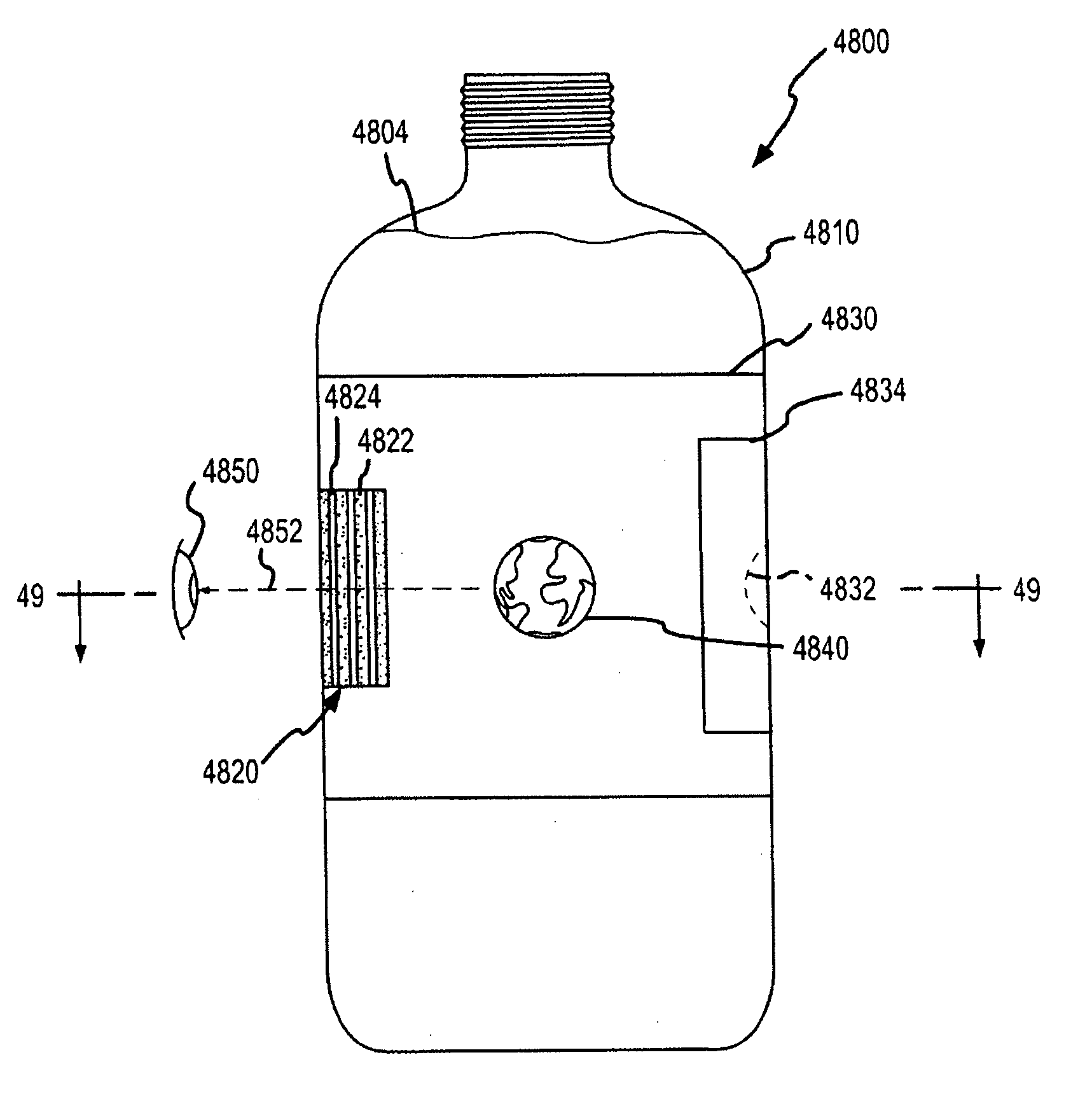
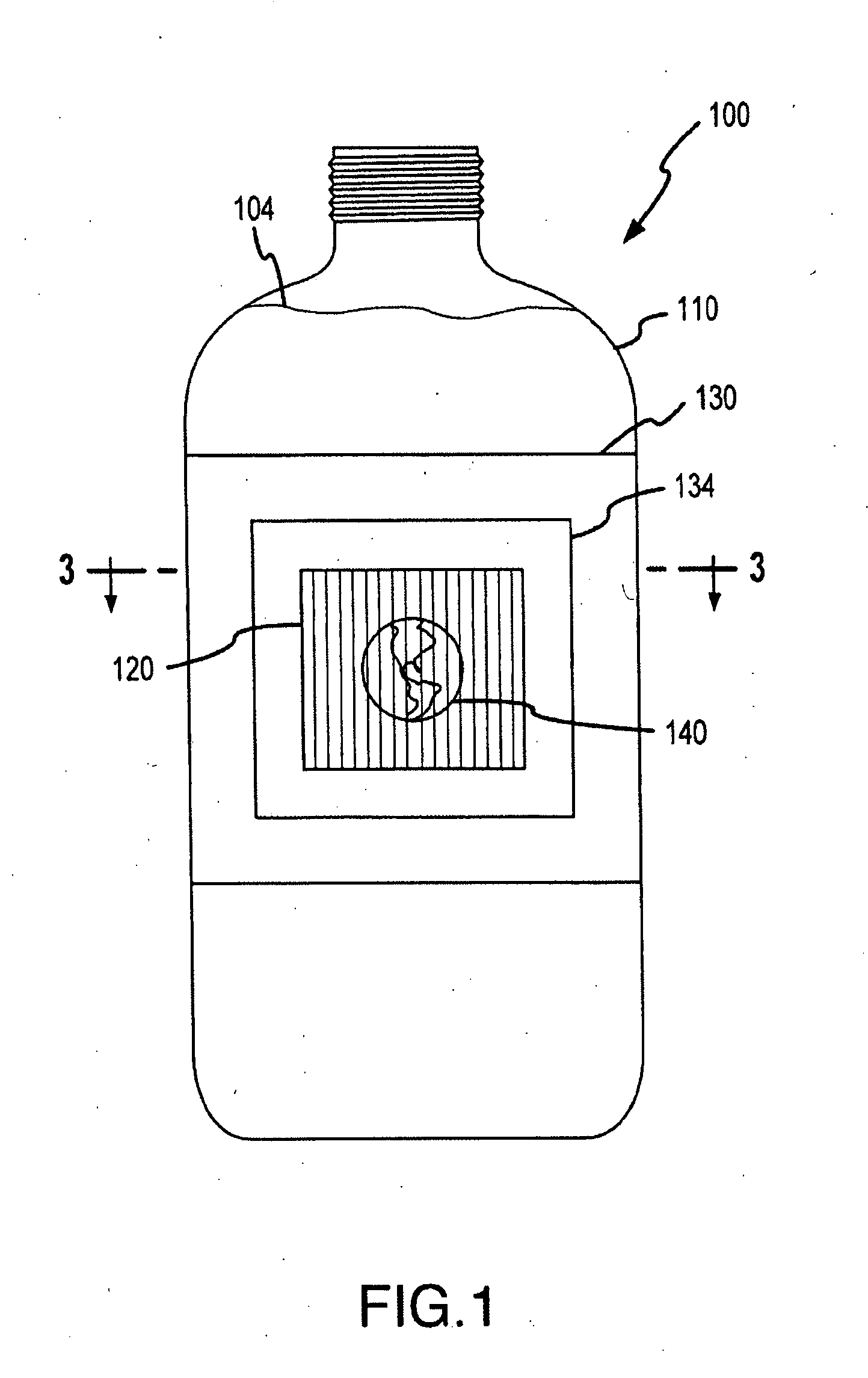
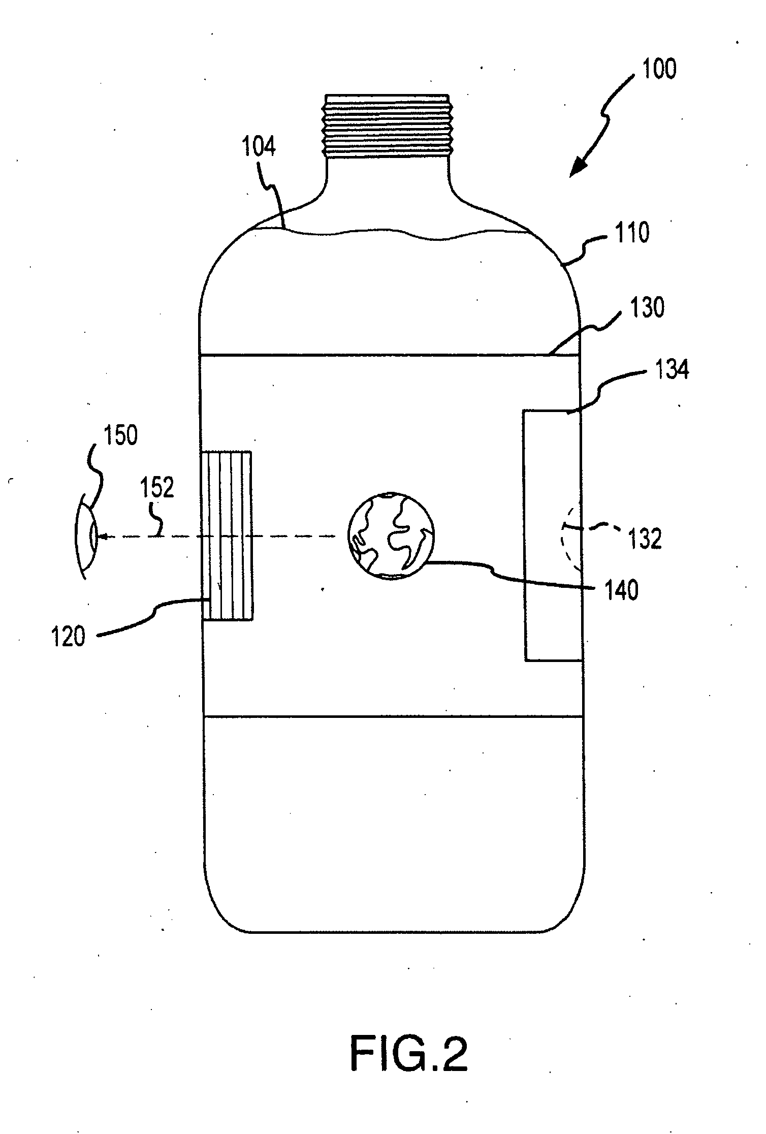
[0070] Many of the embodiments described herein utilize a lenticular lens system or array in combination with a container's or object's sidewalls and contents to achieve desired optical effects with an interlaced image. In some cases, an air gap is created between a lens system, e.g., a lens array provided on a wraparound label, and an interlaced image. The present invention is also directed to providing an alternative way of displaying or allowing viewing of an interlaced image that does not require a lenticular lens array. Specifically, an alternative method of providing animation and 3D imagery with an interlaced image is to substitute a block out grid (or block out assembly or system) for the lenticular lens array or plurality of lenticular lenses. Block out grids typically are considered less useful or desirable than lenticular lens in producing optical effects and imagery. However, the combination of block out grids with the additional “lens” thickness or optical characteristi...


PUM


Abstract

A container for producing a graphical image. The container includes a container wall with front and rear portions. A label is included that extends about the circumference of the container with an inner surface contacting an exterior surface of the rear portion of the container wall and contacting an exterior surface of the front portion of the container wall. The label includes a block out grid made up of alternating block out lines and transparent viewing gaps on the outer or inner surface of the label. The view gaps provide a line of sight to subset of the segments of an interlaced image provided on or proximate to the rear portion of the container wall when the block out grid is positioned near the front portion of the container wall. The label may be used to create an air gap between the block out grid and the interlaced image.

Description

CROSS-REFERENCE TO RELATED APPLICATIONS [0001] This application is a continuation-in-part of U.S. patent application Ser. No. 11 / 386,326, filed Mar. 22, 2006, which is a divisional application of U.S. patent application Ser. No. 11 / 257,191, filed Oct. 24, 2005, which is a divisional application of U.S. patent application Ser. No. 11 / 182,290, filed Jul. 15, 2005, which is a divisional application of U.S. patent application Ser. No. 10 / 925,179, filed Aug. 23, 2004, now U.S. Pat. No. 6,943,953, which is a continuation-in-part of U.S. patent application Ser. No. 10 / 230,751, filed Aug. 29, 2002, now U.S. Pat. No. 6,781,761, and this application is also a continuation-in-part of U.S. patent application Ser. No. 11 / 422,695, filed Jun. 7, 2006. Each of these applications and patents are incorporated herein by reference in their entirety.BACKGROUND OF THE INVENTION [0002] 1. Field of the Invention [0003] The present invention relates, in general, to optical illusions and devices designed to ...

Claims


Application Information

Patent Timeline
Patent Type & Authority Applications(United States)
IPC IPC(8): G02B27/02B65B53/02
CPCB65D23/085G09F3/10G09F3/02B65D2203/02Y10S359/90G02B27/10
Inventor RAYMOND, MARK A.WEISS, SETH
Owner GENIE LENS TECH
Why Eureka
Try Eureka