Laser beam injecting optical device for optical fiber

Inactive Publication Date: 2008-01-24
KK TOSHIBA +1
View PDF1 Cites 11 Cited by
  • Summary
  • Abstract
  • Description
  • Claims
  • Application Information

AI Technical Summary

Benefits of technology

[0011]The present invention has been achieved in consideration of the circumstances, and an object of the invention is to provide a laser beam injecting optical device for optical fiber, which is capable of carryin

Problems solved by technology

Therefore, damage due to an avalanche of electrons or multiphoton absorption is brought about, which instantly breaks the optical fiber, making it difficult to transmit a laser beam (for example, refer to “Laser Handbook”, written by The Laser Society of Japan, Ohmsha Ltd., p463 and p473).
Therefore, a continuous oscillation light is mainly used for laser beam transmission through an optical fiber, and a short pulse laser beam havin

Method used


Image

  • Laser beam injecting optical device for optical fiber
  • Laser beam injecting optical device for optical fiber
  • Laser beam injecting optical device for optical fiber

Examples


Embodiment Construction

[0019]Hereinafter, one embodiment of the present invention will be described with reference to the drawings.

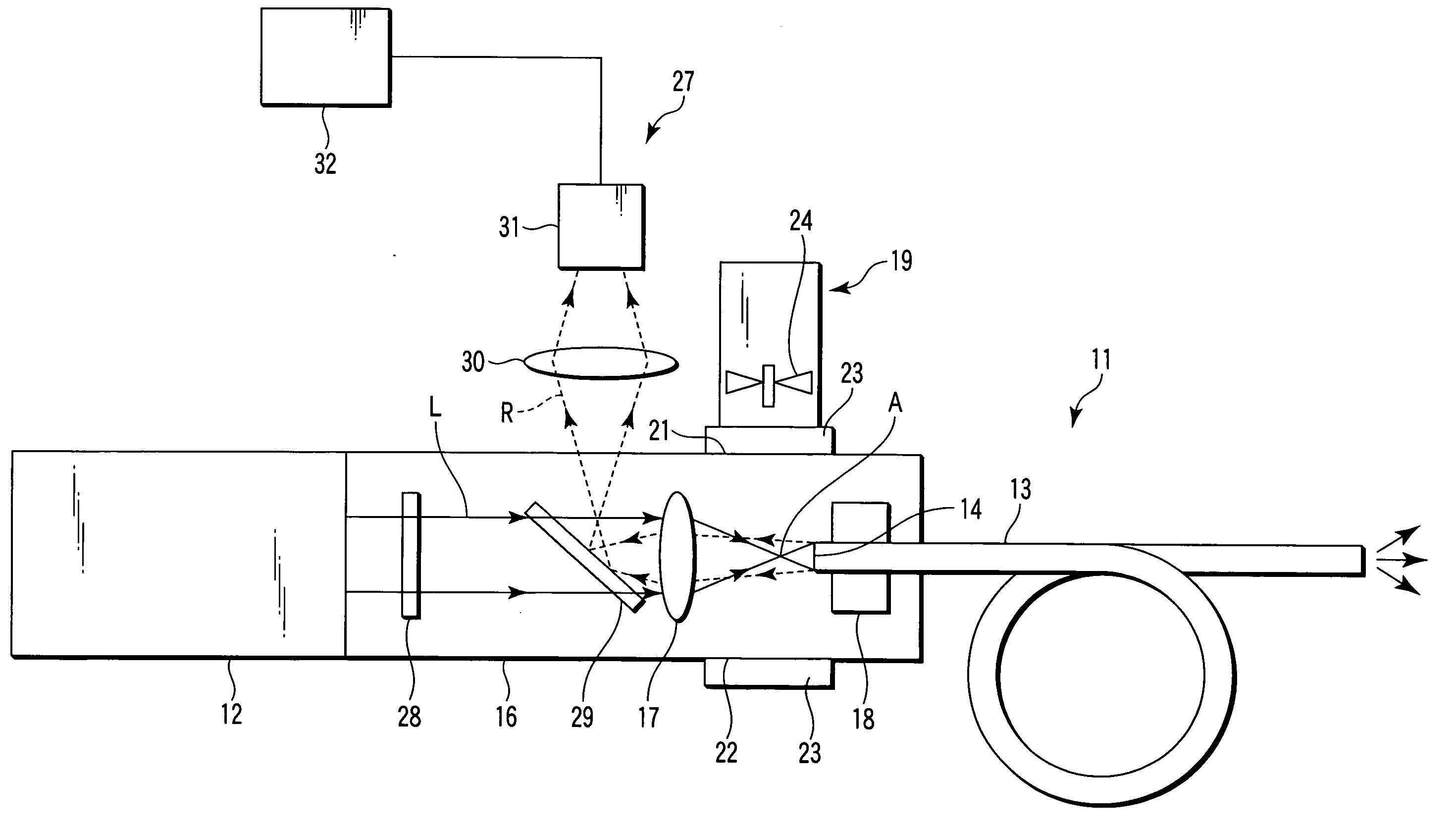
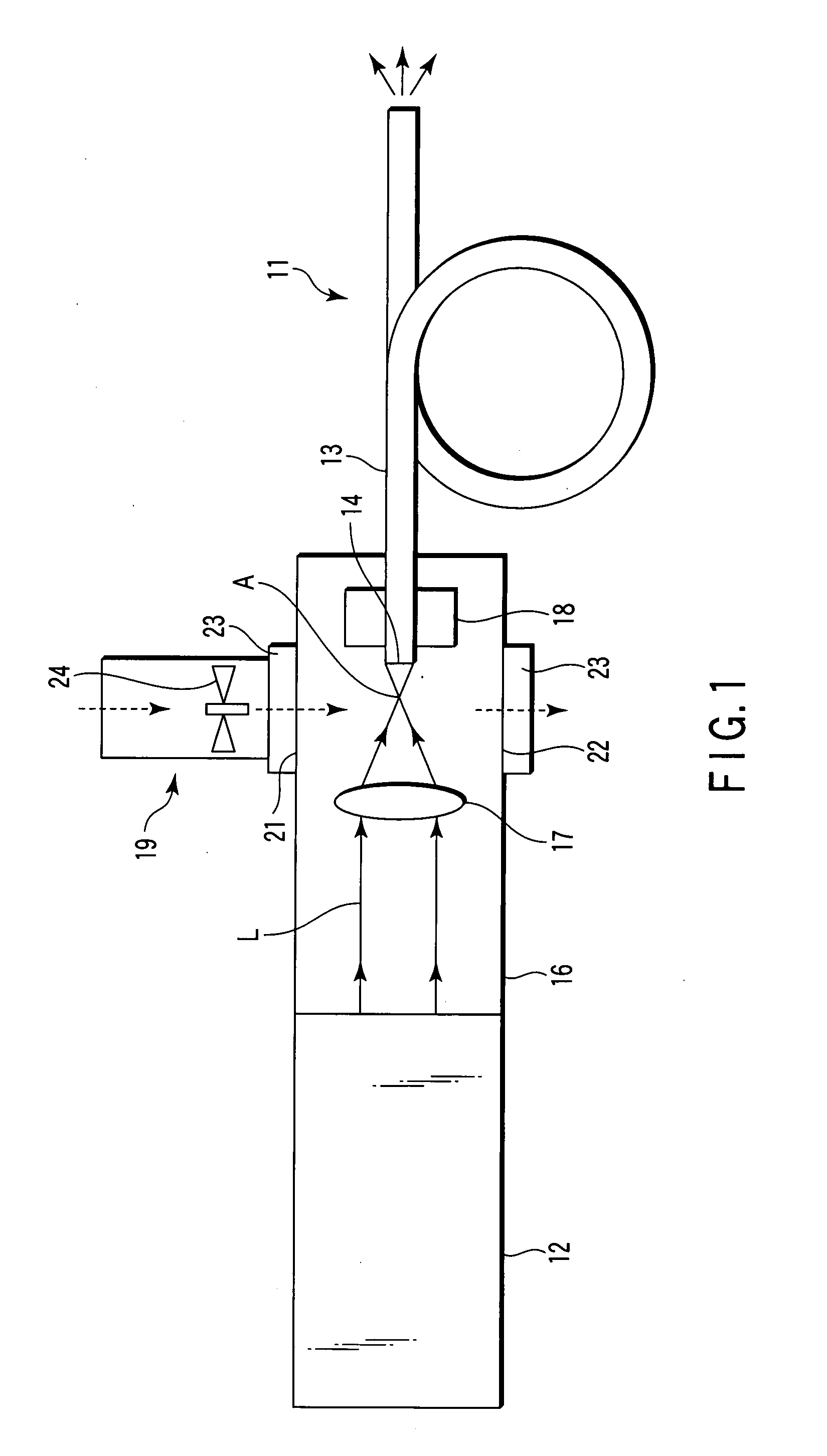
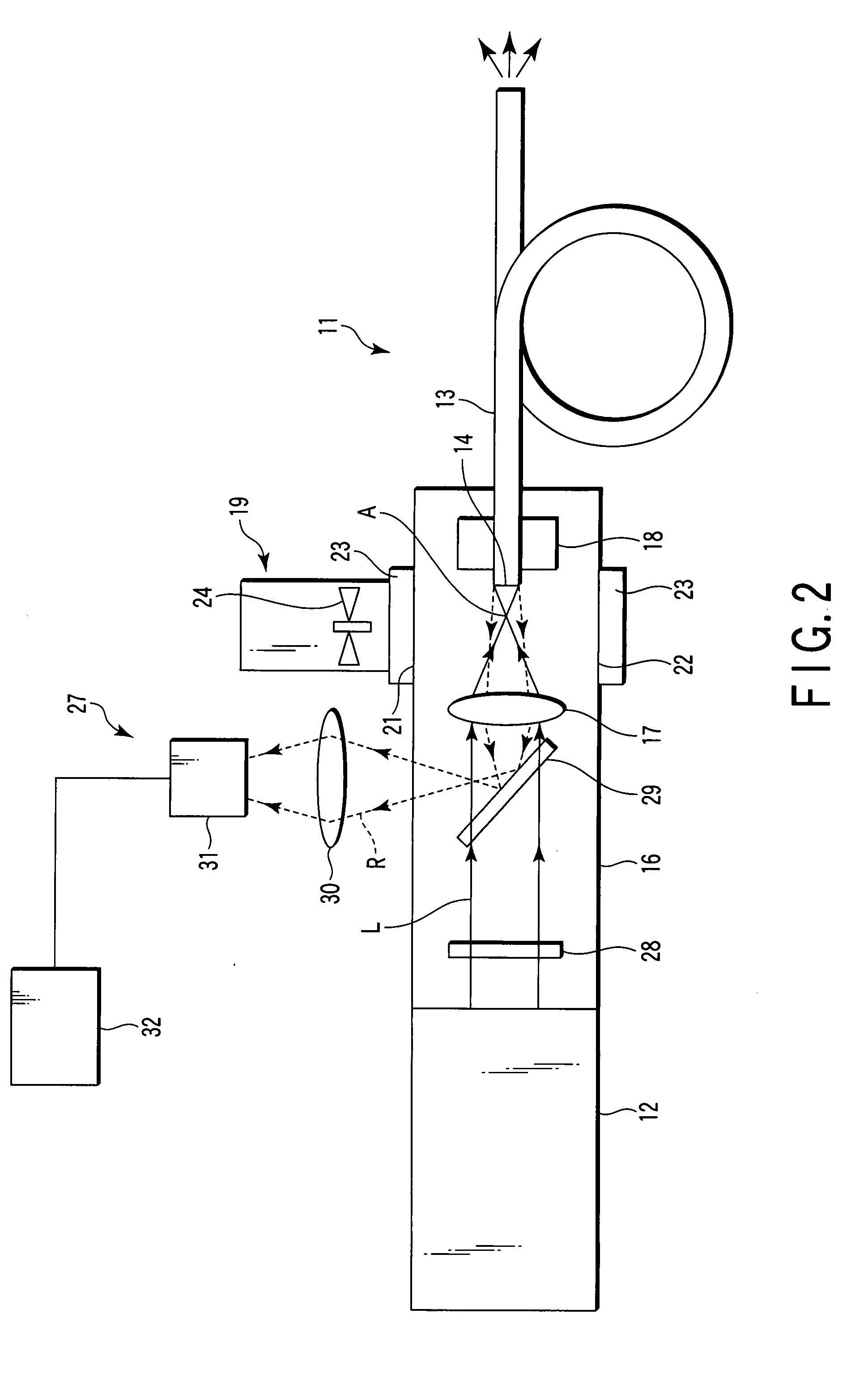
[0020]As shown in FIG. 1, a laser beam injecting optical device for optical fiber 11 is for injecting a laser beam L whose peak power is about 1 MW to 25 MW, serving as a pulse laser beam generated by a laser oscillator 12 serving as a solid-state laser oscillator in a giant-pulse oscillation method, into an entrance end face 14 of an optical fiber 13 with a predetermined core diameter and clad thickness without damaging the optical fiber 13. Further, the laser beam injecting optical device for optical fiber 11 is for making it possible to carry out stable laser beam transmission through the optical fiber 13. Note that, because there is a risk that the optical fiber 13 whose core diameter is about φ1 mm is broken when the peak power of the laser beam L is greater than 25 MW, the peak power is preferably less than or equal to 25 MW.

[0021]The laser beam injecting optical device ...


PUM


Abstract

In a shielding case, a condenser lens condenses a laser beam output by a laser oscillator to inject the laser beam into an entrance end face of an optical fiber disposed posterior to a focusing point of the laser beam. Ventilation of an ambient gas in the shielding case is carried out by ventilating means, and the ambient gas bringing about ionization in the vicinity of the focusing point of the laser beam is eliminated, thereby preventing the outbreak of air breakdown.

Description

CROSS-REFERENCE TO RELATED APPLICATIONS[0001]This application is based upon and claims the benefit of priority from prior Japanese Patent Application No. 2006-196715, filed Jul. 19, 2006, the entire contents of which are incorporated herein by reference.BACKGROUND OF THE INVENTION[0002]1. Field of the Invention[0003]The present invention relates to a laser beam injecting optical device for optical fiber, which injects a laser beam into an optical fiber.[0004]2. Description of the Related Art[0005]Conventionally, in the fields of, for example, laser ablation, laser induced fluorescence analysis, laser peening, and the like, a laser beam, whose peak power is mage greater than or equal to 1 MW, obtained by a giant-pulse oscillation method, has been used.[0006]A step-index optical fiber made of a material containing quartz and having a core diameter of about 1 mm is used for the transmission of such a high-power laser beam, and any continuous oscillation light up to several kW can be tr...

Claims


Application Information

Patent Timeline
IPC IPC(8): H01S3/08
CPCG02B6/4296G02B6/4206
Inventor ISHIBASHI, MAKOTO
Owner KK TOSHIBA
Why Eureka
Try Eureka