High-Pressure Fuel Pump

Active Publication Date: 2008-01-24
HITACHI ASTEMO LTD
View PDF6 Cites 23 Cited by
  • Summary
  • Abstract
  • Description
  • Claims
  • Application Information

AI Technical Summary

Benefits of technology

[0010]In view of the above situation, an object of the present invention is to pr

Problems solved by technology

In this condition, a lubricant (liquid film) formed in a gap between a cylinder and a plunger, which is formed by a part of the pressurized fuel from the pressurizing chamber, may become to be prone to deficient due to the heat generated by the slide of the plunger on a sled face of the cylinder.
It may become a cause of that the sliding face (outer surface) of the plunger and the sled face (inner surface) of the cylinder are seized up or jammed even by the generation o

Method used


Image

  • High-Pressure Fuel Pump
  • High-Pressure Fuel Pump
  • High-Pressure Fuel Pump

Examples


embodiment 1

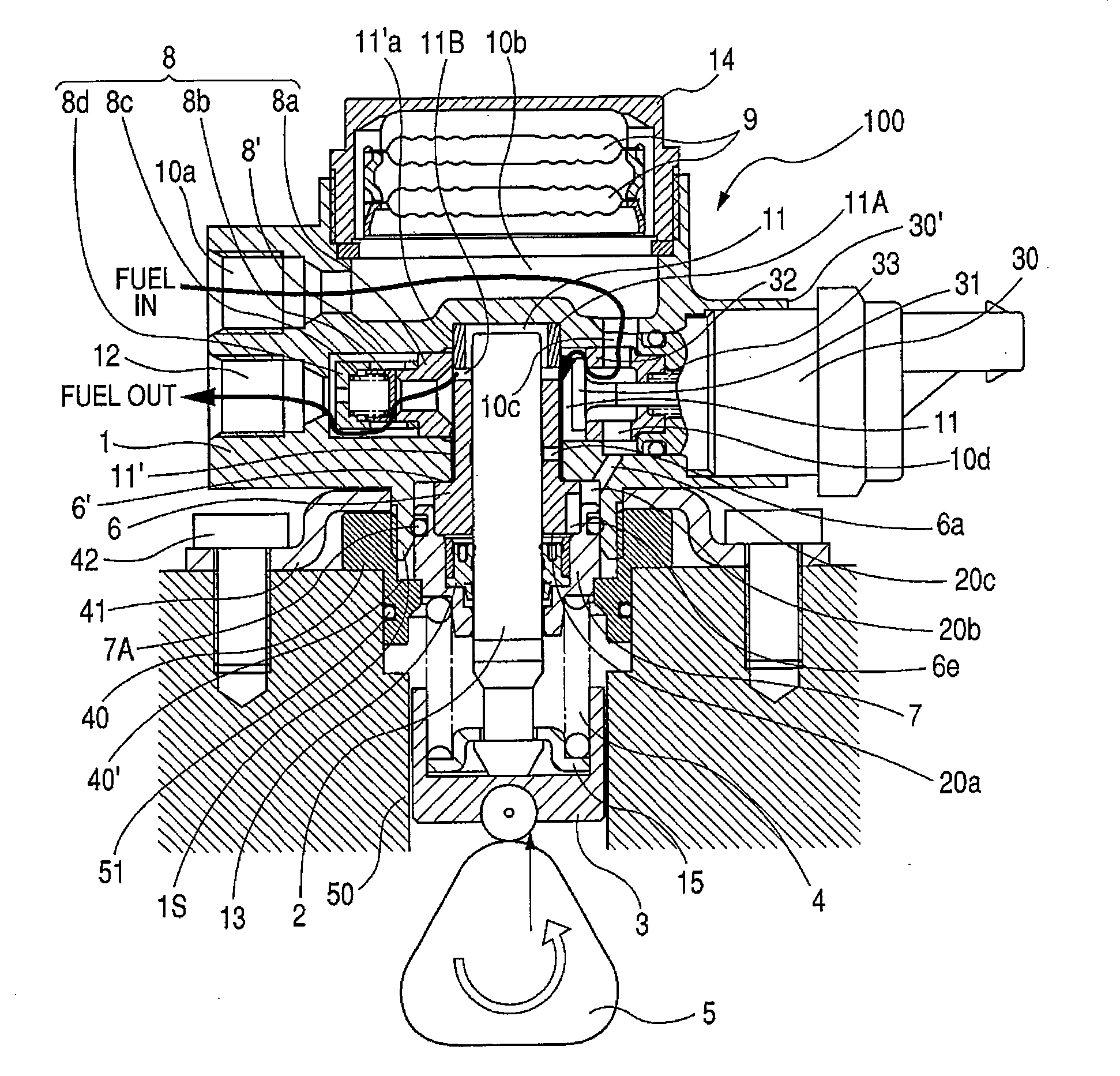
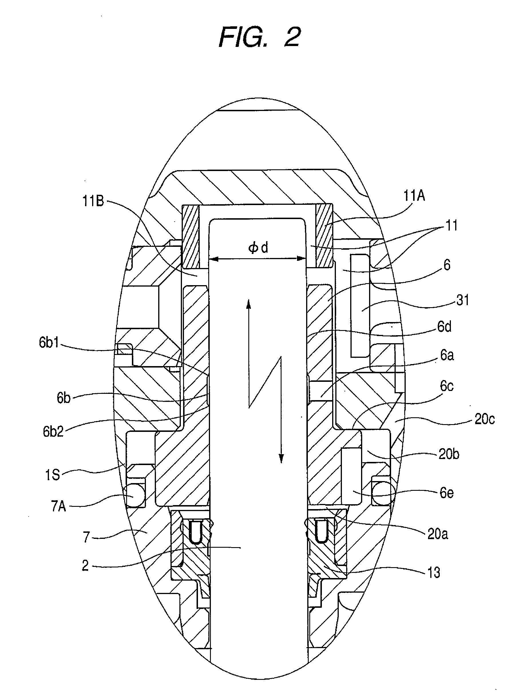
[0019]The first embodiment of the present invention is explained in reference to FIGS. 1 to 6.

[0020]FIG. 1 is a vertical sectional view of a high-pressure fuel pump according to the present invention. FIG. 6 is a view showing a fuel feeding system using the high-pressure fuel pump shown in FIG. 1.

[0021]A fuel sucked up from a fuel tank 20 with a low-pressure feed pump 21 is fed into a fuel inlet 10a of a high-pressure fuel pump 100 through a suction pipe 28. A pressure regulator 22 controls a fluid pressure in the suction pipe 28 to a constant level and controls the amount of the fuel supplied to the high-pressure pump 100. Here, it is also possible to directly control the flow rate of the fuel discharged from the low-pressure pump 21 and control the fluid pressure in place of the installment of the pressure regulator 22.

[0022]The fuel fed in the fuel inlet 10a is taken in a low-pressurizing chamber 10d through a damper room 14 (described later) in which metal dampers 9 are placed a...

embodiment 2

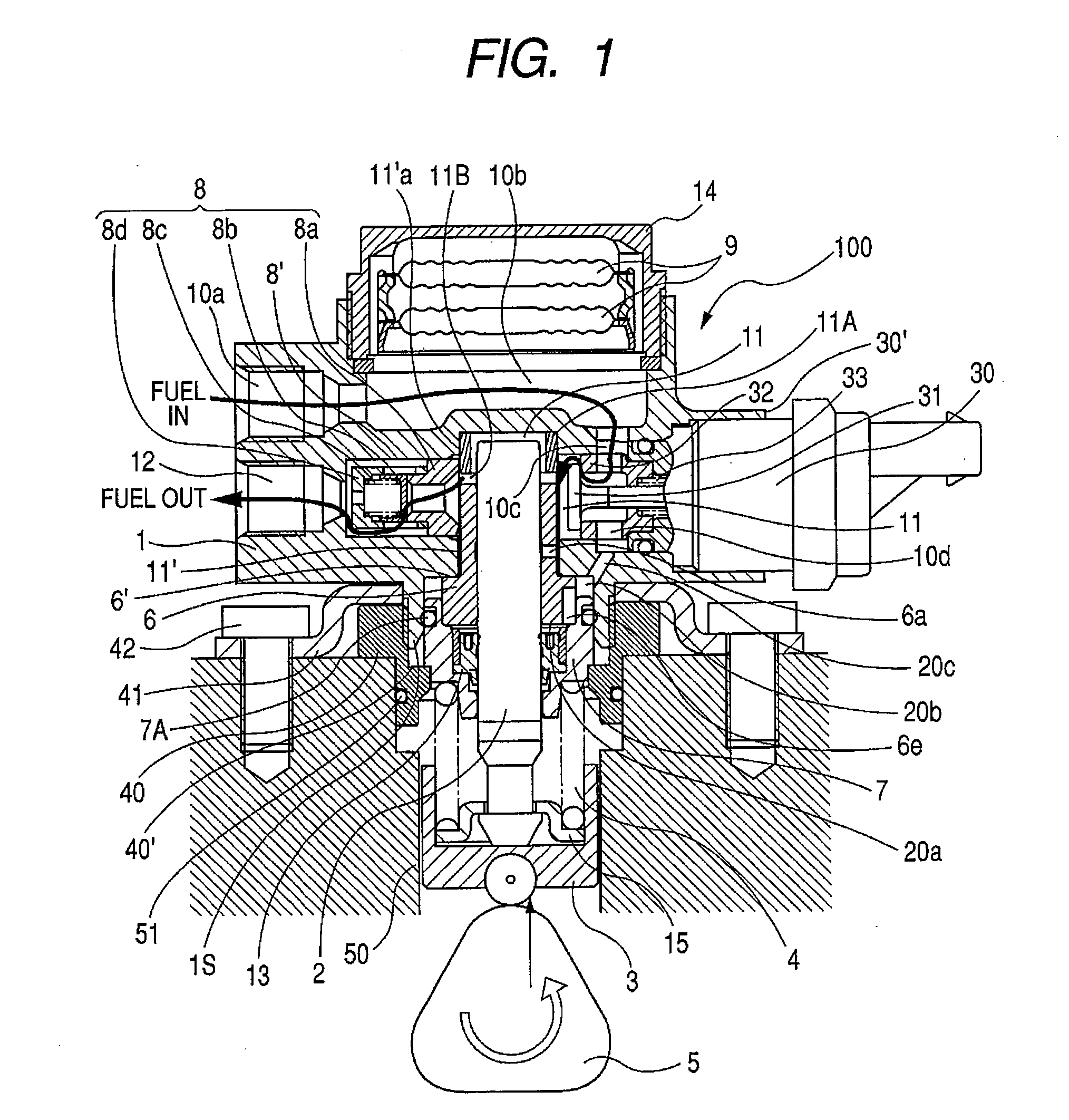
[0073]Here, a configuration of merely increasing the diameter gap (φD−φd) between the plunger 2 and the cylinder 6, leading a high-pressure fuel coming from the pressurizing chamber 11 to the gap between outer surface of the plunger 2 and the inner face of the cylinder 6 from the top end of the cylinder 6, and thus increasing the amount of the high-pressure liquid may be adopted. The configuration has the fear of increasing the leaning of the plunger 2 and increasing the amount of leakage from the pressurizing chamber 11 to the fuel reservoir 20a, and hence can be applied to a device that does not have such fear.

embodiment 3

[0074]Further, it is also effective either to partially form a gap (1) larger than the gap (2) for the guide of the plunger or to form a straight vertical groove or a spiral groove at any part of either surface where the outer surface of the plunger 2 and the inner surface of the cylinder 6 face to each other as a communicating pass leading the pressurized fluid to the slide face. The configuration is more effective since a circulation channel is formed by combining the configuration with the configuration of forming a transverse hole 6a in the cylinder 6 or the configuration of further forming an annular groove 6b in the cylinder 6, those two configurations being explained earlier.

[0075]In the present embodiment, the diameter gap for plunger guide is at most about 10 μm and hence the inclination of the plunger 2 never increases. Further, the seal lengths of the plunger 2 and the cylinder 6 in the high-pressure and the low pressure can be substantially identical in comparison with t...


PUM


Abstract

A high-pressure fuel pump is comprises of: a plunger which slidably fits to a cylinder and reciprocates for pressurizing and discharging a fuel taken in a pressurizing chamber; an inlet valve device for taking in a fuel into the pressurizing chamber; an outlet valve device for discharging the pressurized fuel from the pressurizing chamber; and a communicating pass which comprises a hole or a groove formed in the cylinder, and communicates between a pressurized fuel area and a gap between the cylinder and the plunger.

Description

CLAIM OF PRIORITY[0001]The present application claims priority from Japanese application serial no. 2006-197558 filed on Jul. 20, 2006, the contents of which are hereby incorporated by reference into this application.TECHNICAL FIELD [0002]The present invention relates to a fuel supply pump in an internal combustion engine for an automobile, and in particular to a high-pressure fuel pump which supplies a high-pressure fuel to a fuel injection valve in an in-cylinder fuel injection type internal combustion engine.BACKGROUND ON THE INVENTION [0003]A high-pressure fuel pump to which the present invention is applicable, has a plunger slidably fits to a cylinder and a pressurizing chamber whose volumetric capacity can be variable by a reciprocation of the plunger. The plunger pressurizes a fuel led into the pressurizing chamber through an inlet valve device, and discharges the fuel through an outlet valve device.[0004]As a high-pressure pump of this type, the following types are known. On...

Claims


Application Information

Patent Timeline
IPC IPC(8): F04B39/10
CPCF02M59/102F02M59/265F04B1/0421F02M63/0225F02M2200/02F02M63/0001
Inventor HASHIDA, MINORUYAMADA, HIROYUKISHIMADA, JUNICHIONOSE, TORUUSUI, SATOSHIABE, MASAMIHIMOTO, TOHRU
Owner HITACHI ASTEMO LTD
Why Eureka
Try Eureka