Connector for coaxial cable and method

Inactive Publication Date: 2008-01-24
JOHN MEZZALINGUA ASSOC INC
View PDF35 Cites 13 Cited by
  • Summary
  • Abstract
  • Description
  • Claims
  • Application Information

AI Technical Summary

Benefits of technology

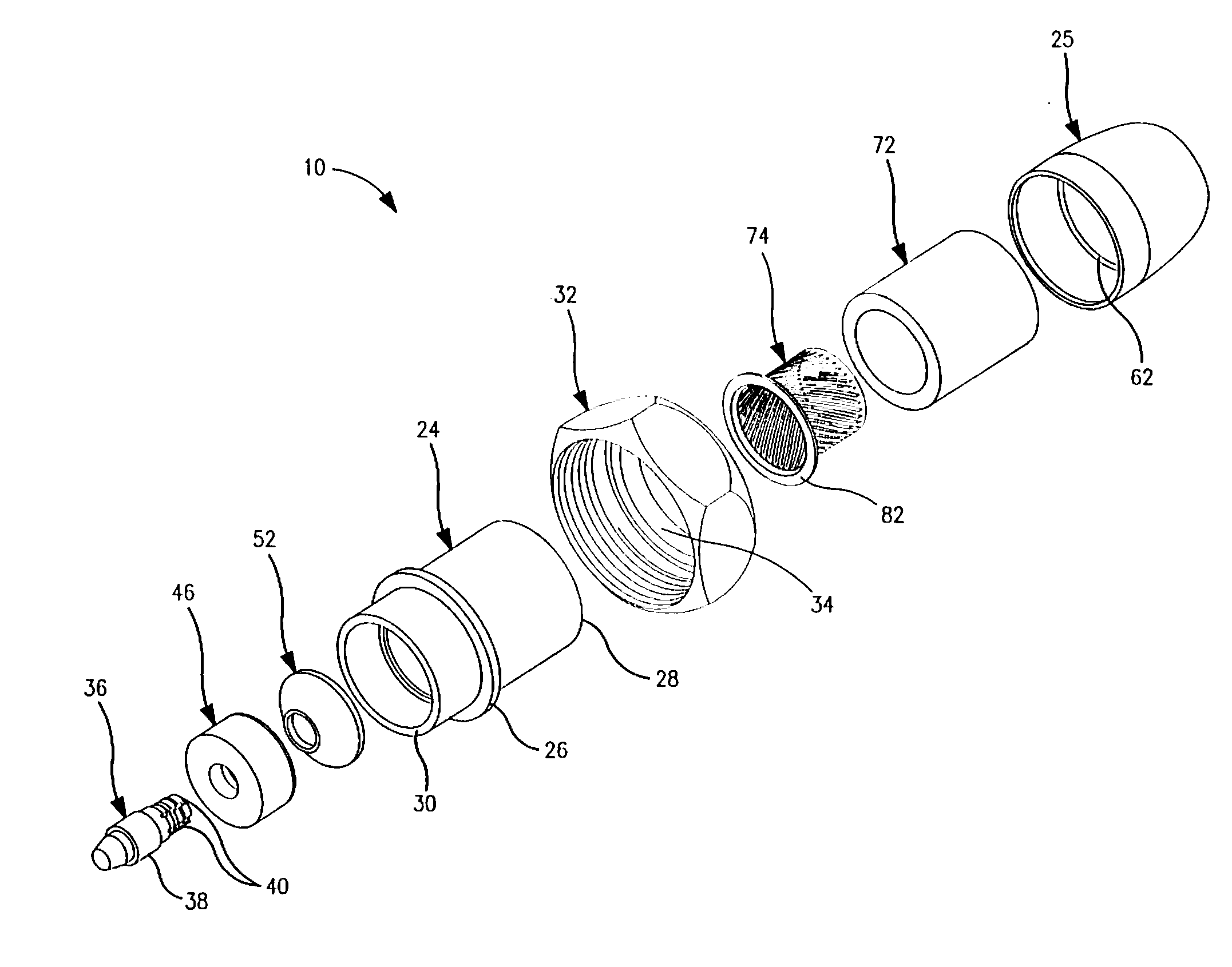
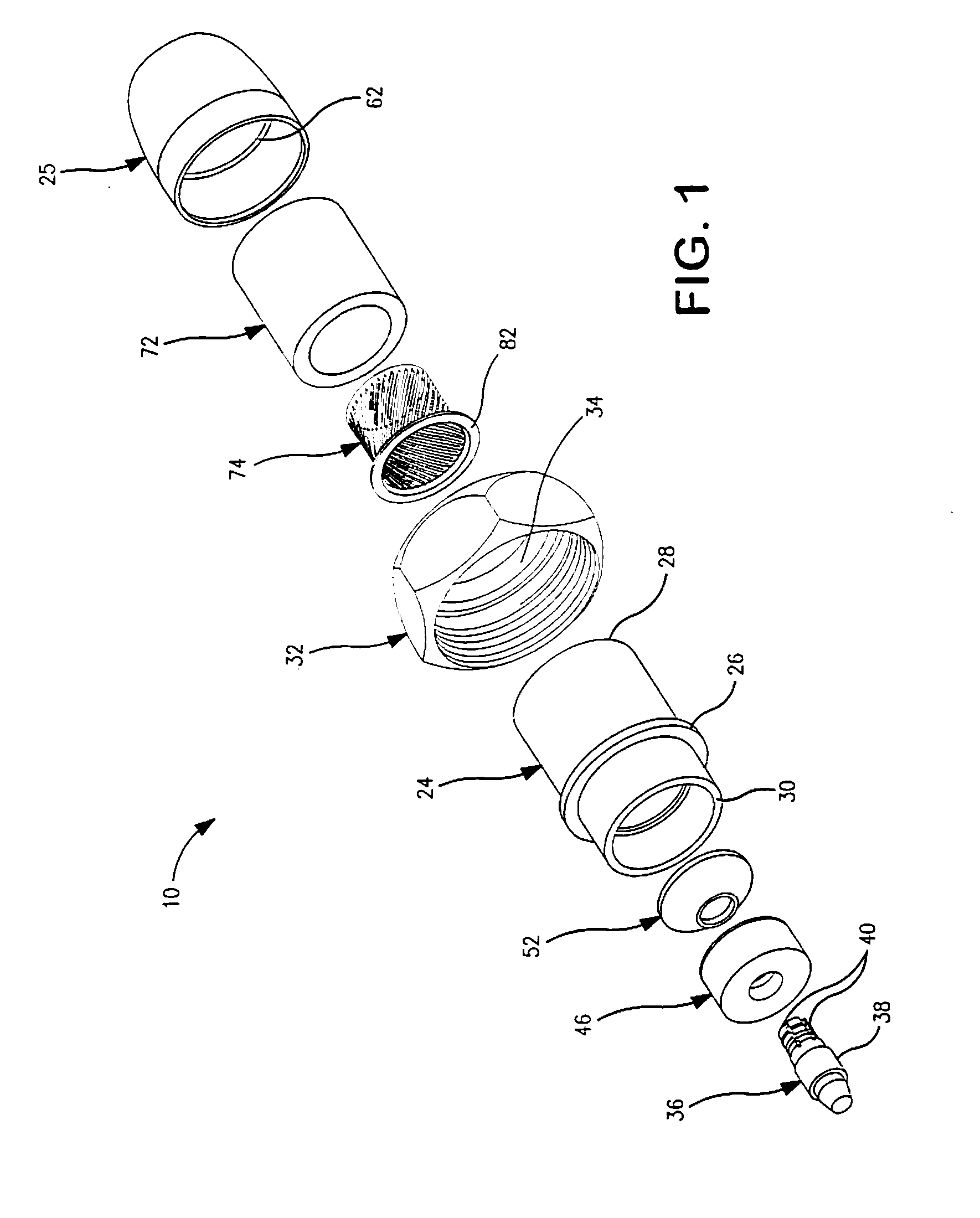
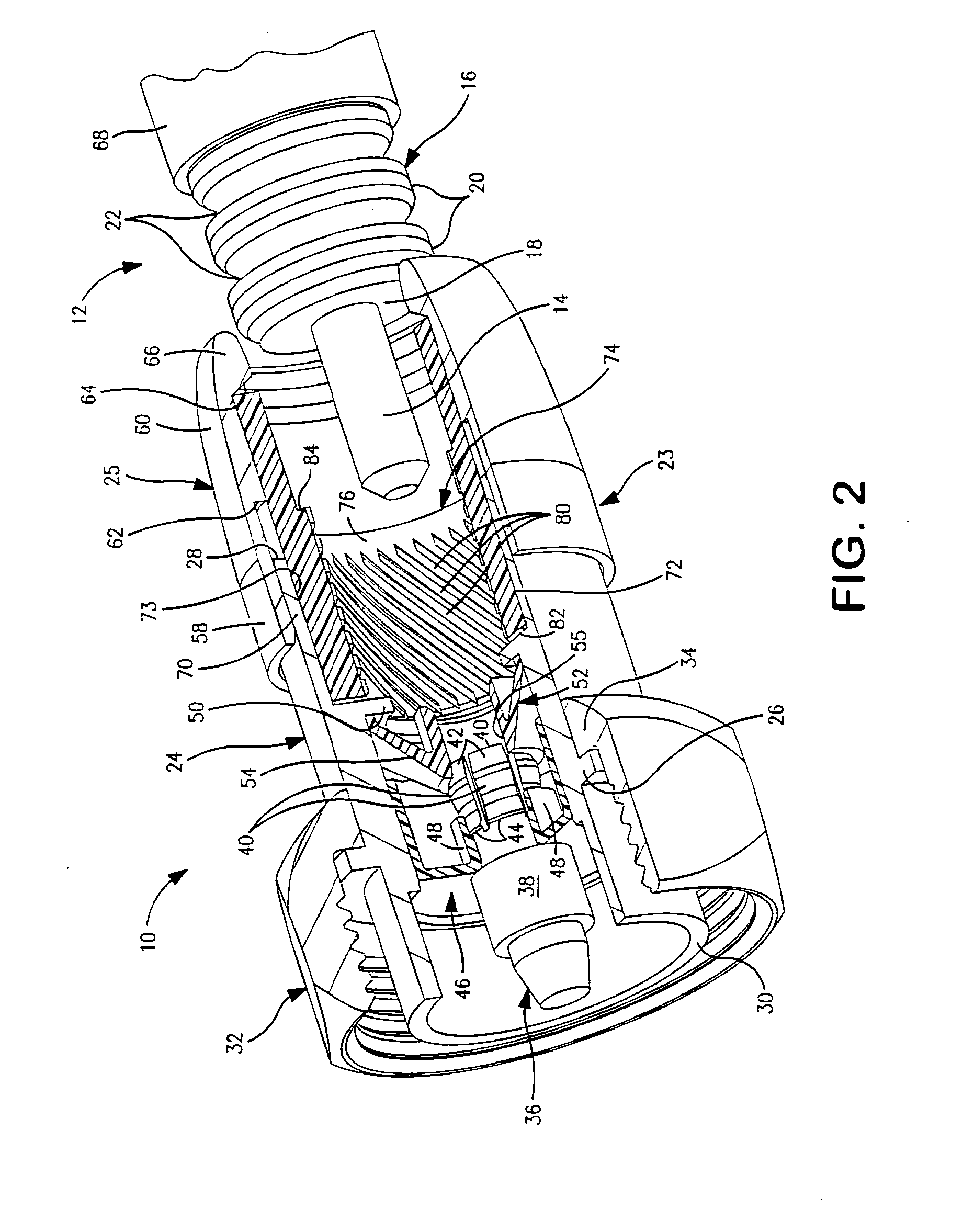
[0015]Mounting of the connector on the cable forms reliable electrical connections with the inner and outer cable conductors and a strong physical connection between the connector and the cable. The physical connection extends along an appreciable length of the cable. The elastomer is deformed radially inwardly to hold the conductive member

Problems solved by technology

It is difficult and time consuming to attach a conventional coaxial connector to the end of corrugated coaxial cable.
The physical connection between the connector and cable is not strong and may fail and break the electrical connections.
Mounting of conventional corrugated cable connectors in the field is difficult, particula

Method used


Image

  • Connector for coaxial cable and method
  • Connector for coaxial cable and method
  • Connector for coaxial cable and method

Examples


Example

[0051]Second embodiment connector 114 shown in FIG. 9 forms electrical connections with corrugated coaxial cable 116. The connector 114 is similar to connector 10. The cable may be identical to cable 12 or, alternatively, may have spiral wound outer corrugations.

[0052]Connector 114 has a two-part tubular metal body 119 formed from tubular body members 120 and 121. Member 120 has an outwardly extending flange 122 located between the port end of the member and radially inwardly extending flange 124 at the cable end of the member. Bushing 126 is seated in the interior of the member and holds collar 128 and ring 130 in place in the body with the ring abutting flange 124. Collar 128 and ring 130 are similar to previously described collar 46 and ring 52. The collar and ring hold contact pin 132 in body 120. Pin 132 is identical to pin 36. Member 121 is mounted on the exterior surface of member 120 between flanges 122 and 124. Member 121 is tubular and includes a cylindrical inner surface ...

Example

[0056]Third embodiment connector 214 shown in FIGS. 10-13 forms electrical connections with smooth coaxial cable 216.

[0057]Connector 214 is similar to connector 114 and includes a two-part tubular metal body 218 identical to body 119. A thin wall cylindrical conductive member 220 is mounted within unstressed elastomer tube or member 222. Conductive member 220 is identical to the previously described conductive member 86, but conductive members 74 or 88 could be used. Elastomer tube 222 is identical to elastomer tube 150. A tubular conductive elastomer member such as member 105 could be used instead of a separate conductive member and elastomer tube.

[0058]Contact pin 224 includes a collar 226 adjacent contact fingers 228. Collar 226 has a radially enlarged end 230 immediately adjacent the fingers 228. Bushing 232 is seated in the interior of the connector and holds alignment collar 234 and ring 236 in place with flange 238. Ring 236 is like ring 48. Alignment collar 234 has a tubular...


PUM


Abstract

An electrical connector is mounted on a coaxial cable. An electrical connection with the outer conductor of the cable is formed by compressing an elastomer body surrounding the end of the cable and pressing the body inwardly against the cable to hold a conductive member in electrical connection with the outer conductor.

Description

[0001]This application is a continuation-in-part of my co-pending U.S. application Ser. No. 11 / 458,475 filed Jul. 19, 2006.FIELD OF THE INVENTION[0002]The invention relates to connectors for mounting on the ends of coaxial cables to establish electrical connections with the inner and outer conductors in the cables, and to methods for mounting connectors on the ends of coaxial cables.BACKGROUND OF THE INVENTION[0003]Coaxial cable is commonly used to carry high frequency electrical signals. In the wireless and cellular telephone industries coaxial cable is used to transmit power signals from amplifiers to antennas on the tops of towers and for radio transmitter applications. The cable is typically about to 2″ in diameter and includes a metal central conductor surrounded by a metal outer conductor. Foam insulation fills the space between the conductors.[0004]The coaxial cable may be a smooth coaxial cable having a smooth outer conductor, or may be a corrugated coaxial cable having a co...

Claims


Application Information

Patent Timeline
IPC IPC(8): H01R9/05
CPCH01R4/4881H01R9/0524H01R2103/00H01R13/622H01R24/564H01R9/0527
Inventor MONTENA, NOAH P.
Owner JOHN MEZZALINGUA ASSOC INC
Why Eureka
Try Eureka