Multi-lumen catheter with separate distal tips

a catheter and distal tip technology, applied in the field of multi-lumen catheters, can solve problems such as blood clots, problems such as loss of catheter function, and become problematic, and achieve the effects of reducing dead space, improving flow characteristics, and providing ease of delivery

Active Publication Date: 2008-01-24
CR BARD INC
View PDF99 Cites 60 Cited by
  • Summary
  • Abstract
  • Description
  • Claims
  • Application Information

AI Technical Summary

Benefits of technology

[0018] One improvement to prior art split-tip catheters comprises a unique configuration of each tip section to improve flow characteristics, provide ease of delivery and overcome typical problems associated with hemodialysis catheters. In a dual lumen embodiment, the split-tip catheter comprises a shorter arterial tip section comprising a semi-cylindrical shape with a rounded distal end, and a longer venous tip section comprising a semi-cylindrical shape in a proximal portion which smoothly transitions in a transition region to a cylindrical shape in a distal portion, the cross-sectional size of the distal portion being greater than the cross-sectional size of the proximal portion, the distal portion terminating in an inward bevel. Another improvement comprises the strategic placement of openings placed on the tip sections of the split-tip catheter. With particular respect to an arterial tip section in a dual lumen configuration, the openings are of...

Problems solved by technology

The primary problems occurring in dual lumen dialysis catheters are blood clotting (thrombosis) and fibrin (the protein formed during normal blood clotting that is the essence of the clot) sheath formation.
Thrombus and fibrin sheath formation can occlude distal tips of the dialysis catheter lumens, resulting in loss of catheter function when such an occlusion prevents blood flow.
A secondary problem relates to the arterial lumen “sucking” against the vessel wall, in wh...

Method used


Image

  • Multi-lumen catheter with separate distal tips
  • Multi-lumen catheter with separate distal tips
  • Multi-lumen catheter with separate distal tips

Examples


Embodiment Construction

[0057] The following detailed description should be read with reference to the drawings, in which like elements in different drawings are identically numbered. The drawings, which are not necessarily to scale, depict selected preferred embodiments and are not intended to limit the scope of the invention.

[0058] The detailed description illustrates by way of example, not by way of limitation, the principles of the invention. This description will clearly enable one skilled in the art to make and use the invention, and describes several embodiments, adaptations, variations, alternatives and uses of the invention, including what is presently believed to be the best mode of carrying out the invention.

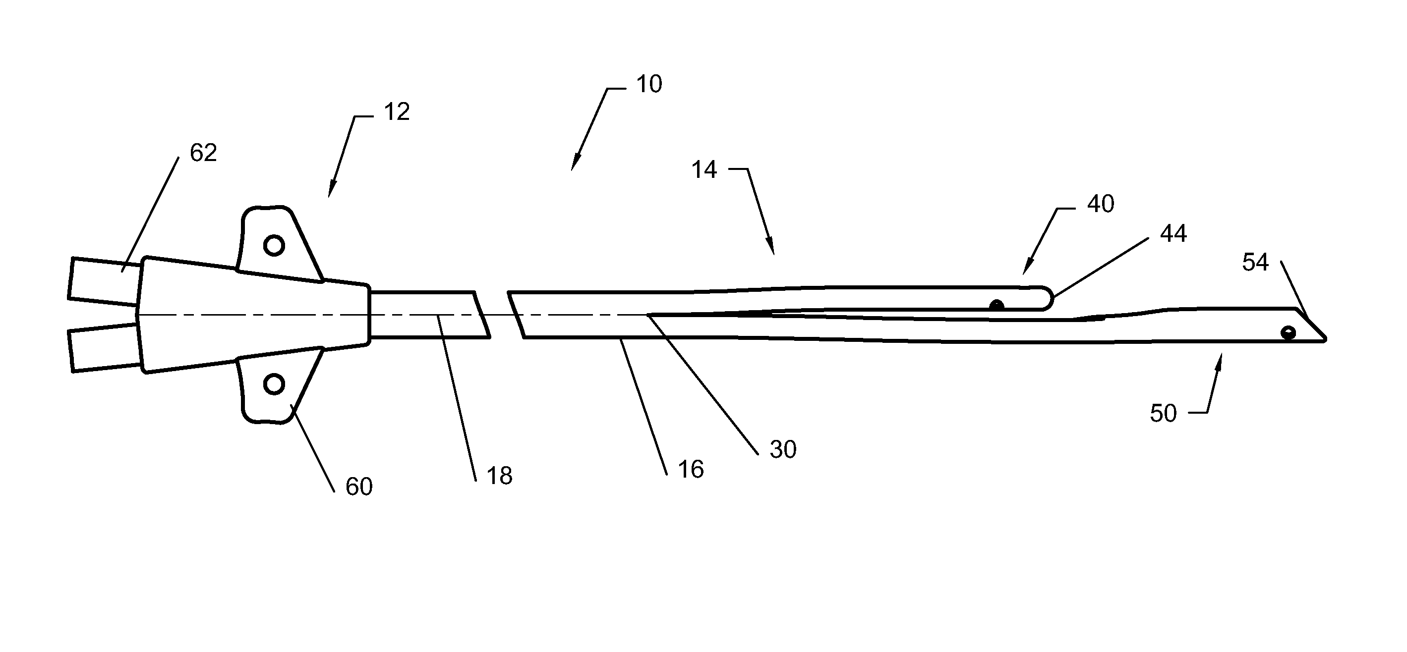
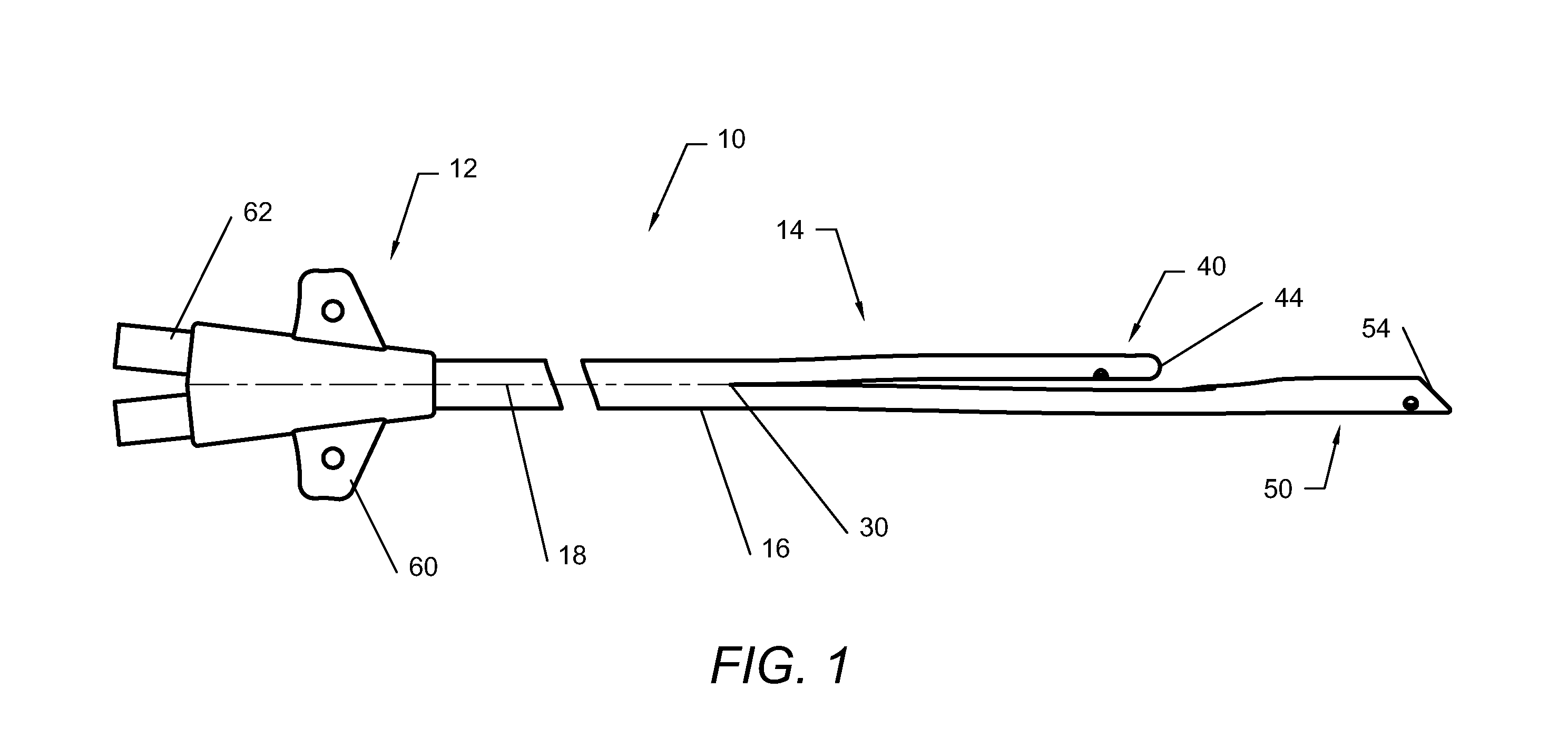
[0059] The present invention is directed to multi-lumen catheters with separate distal tips in the form of improvements over prior art split-tip catheters as well as new configurations and embodiments. While the examples and embodiments of a multi-lumen catheter are discussed herein in ter...


PUM

PropertyMeasurementUnit
Lengthaaaaaaaaaa
Sizeaaaaaaaaaa
Adhesivityaaaaaaaaaa

Abstract

A multi-lumen catheter including tip sections distal to a dividing point, the tip sections releasably joined by a method that produces a variable separation force between the tip sections along a length thereof. An increasing separation force may be imparted to the tip sections by providing an increasing bond strength in fusion zones from a distal portion of the tip sections toward the dividing point.

Description

PRIORITY [0001] This application is a division of U.S. patent application Ser. No. 10 / 371,774, filed Feb. 21, 2003, which is incorporated by reference into this application as if fully set forth herein.FIELD OF THE INVENTION [0002] The present invention relates generally to a multi-lumen catheter having a plurality of separate distal tips and more particularly to an improved split-tip catheter. BACKGROUND OF THE INVENTION [0003] Multi-lumen catheters are used for the purpose of creating two or more separate fluid pathways, such as in hemodialysis applications. A primary goal of hemodialysis access is to provide a reliable and effective means of dialysis, which means that a sufficient volume of blood over a period of time must be removed from and returned to the patient. Because the contaminated and cleansed blood must be kept separate for an effective dialysis procedure, a dual lumen catheter is generally used. These dual lumen catheters are usually configured so that there is a sho...

Claims


Application Information

Patent Timeline
IPC IPC(8): A61M25/16A61M1/36A61M25/00A61M25/14
CPCA61M1/3653A61M25/007A61M2025/0031A61M25/0074A61M25/0009A61M1/3661A61M25/0026A61M2025/0037A61M1/3659
Inventor ZAWACKI, JOHN A.POWERS, KELLY B.EVAN, JOHN G.ROME, GUY
Owner CR BARD INC
Why Eureka
Try Eureka