Moving Coil Actuator For Middle Ear Implants

a technology of moving coil actuator and middle ear implant, which is applied in the direction of electrical transducers, internal electrodes, electrotherapy, etc., can solve the problems of destroying mechanical fixation destroying the transducer, etc., and achieves the effect of improving the hearing of a patien

Inactive Publication Date: 2008-01-24
MED EL ELEKTROMEDIZINISCHE GERAETE GMBH
View PDF20 Cites 98 Cited by
  • Summary
  • Abstract
  • Description
  • Claims
  • Application Information

AI Technical Summary

Benefits of technology

[0013] Another aspect of the invention is a method for improving the hearing of a patient that includes implanting a coil into the ear of the patient, and securely attaching a permanent magnet to a bone of the patient in a location that is proximal to the coil, so that the magnetic fields of the magnet and the coil interact under the control of the electrical audio signal to displace the coil and, as a result, transmit mechanical stimulation to the inner ear.

Problems solved by technology

The implanted magnet experiences a torque (T=m×B) that may twist the electromagnetic transducer out of its position, thereby injuring the implant wearer and / or destroying the mechanical fixation.
Due to the external magnetic field, the implanted magnet becomes partly demagnetized and this may lead to damage or at least to a reduced power efficiency of the electromagnetic transducer after exposure to the MRI field.
Radio frequency (RF) pulses (magnetic field B1 in MRI) emitted by the MRI unit can induce voltages in the coil(s) of the electro-magnetic transducer and this may destroy the transducer and / or may harm the patient.

Method used


Image

  • Moving Coil Actuator For Middle Ear Implants
  • Moving Coil Actuator For Middle Ear Implants
  • Moving Coil Actuator For Middle Ear Implants

Examples


Embodiment Construction

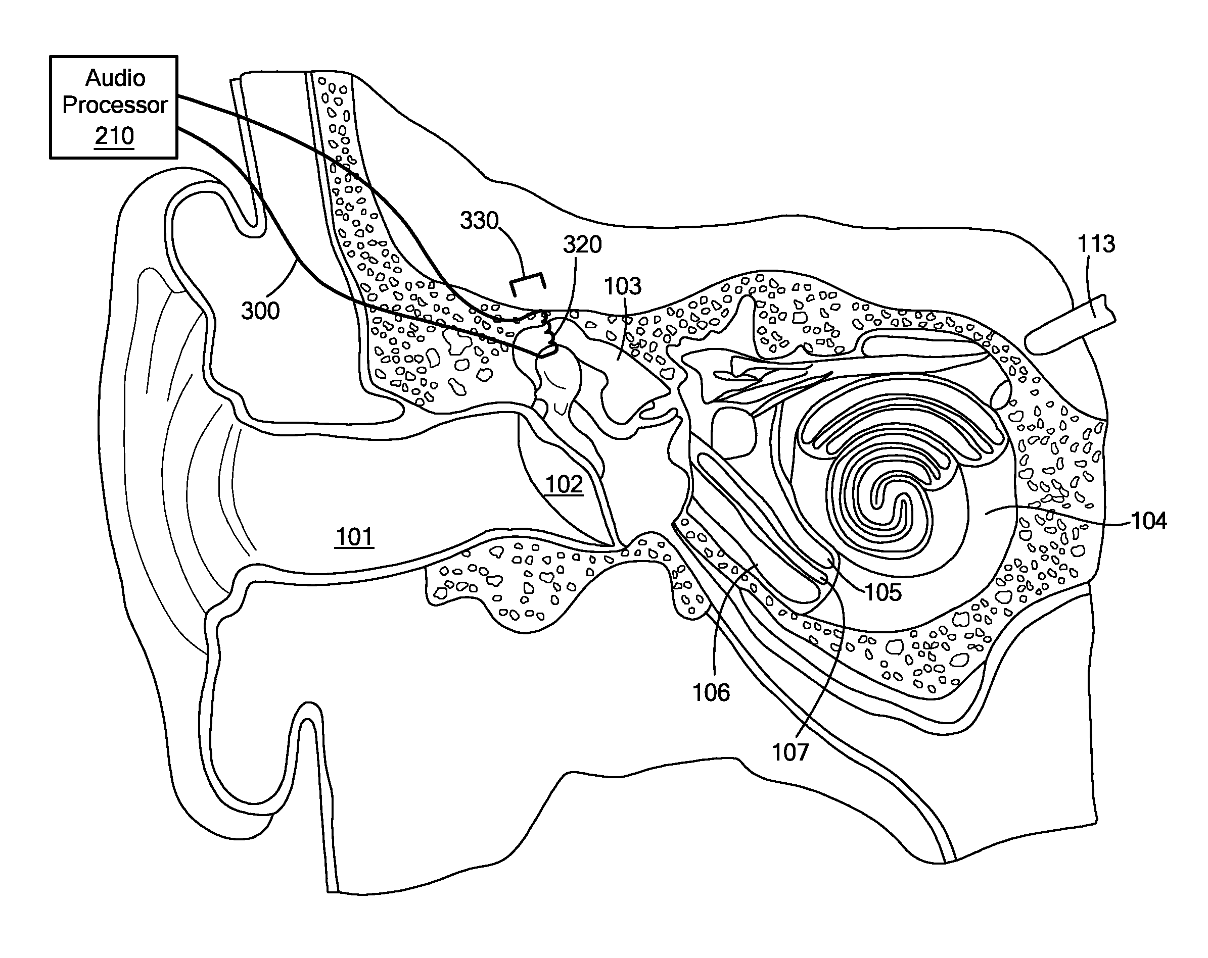
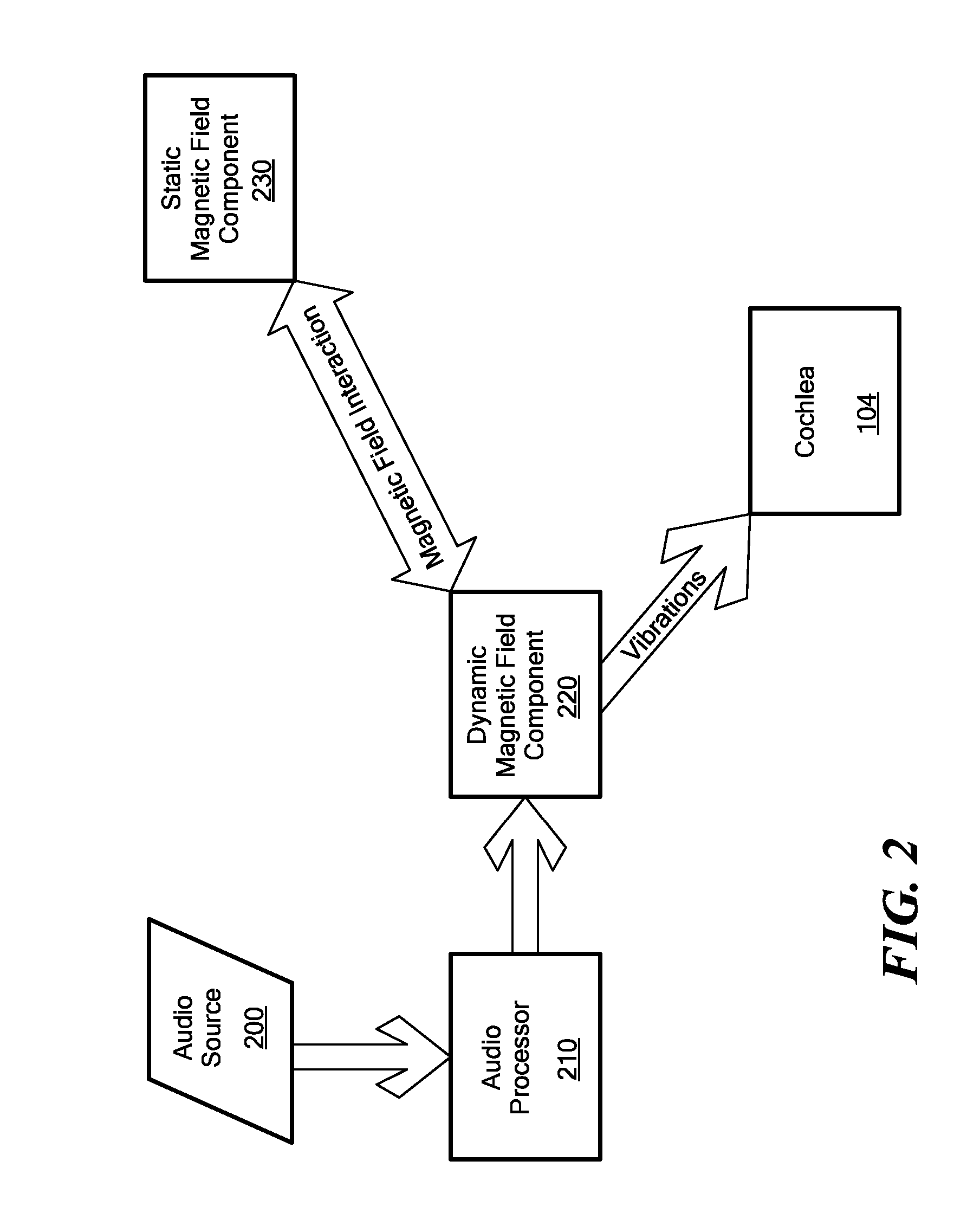
[0018] Illustrative embodiments of the present invention relate to an implant system for enhancing the hearing of a patient A general functional layout of an implant system is shown in the block diagram of FIG. 2. A static magnetic field component 230 and a dynamic magnetic field component 220 are positioned in magnetic proximity to each other. Additionally, one of the components (the dynamic component as shown here) is mechanically coupled to an anatomical structure that is in mechanical signal communication with the cochlea. For example, the dynamic component may be attached to an anatomical structure of the middle ear or to a membrane of the middle ear or inner ear. An audio processor 210 receives an audio signal from an audio source 200 and produces an electrical audio signal that actuates the dynamic magnetic field component 220 to produce a changing magnetic field. The dynamic magnetic field produced by the dynamic magnetic field component 220 interacts with the static magneti...


PUM


Abstract

A hearing enhancement includes an audio processor that generates an electrical audio signal and transmits the signal to a coil. The coil is implanted into a patient in a position that results in transmission of mechanical stimulation to the inner ear when the coil is spatially displaced. A permanent magnet is placed in proximity to the coil so that when the coil receives the electrical audio signal form the processor, the induced coil magnetic field in the coil interacts with the magnetic field from the permanent magnet to spatially displace the coil and, as a result, transmit the mechanical stimulation to the inner ear.

Description

[0001] The present application claims priority from U.S. Provisional Patent Application 60 / 832,821, filed Jul. 24, 2006, the contents of which are incorporated herein by reference.FIELD OF THE INVENTION [0002] The present invention relates to improving hearing for the hearing-impaired. BACKGROUND ART [0003]FIG. 1 shows the anatomy of a normal human ear. A normal ear transmits sounds through the outer ear 101 to the eardrum 102, which moves the bones of the middle ear 103, which in turn excites the cochlea 104. The cochlea (or inner ear) 104 includes an upper channel known as the scala vestibuli 105 and a lower channel known as the scala tympani 106, which are connected by the cochlear duct 107. In response to received sounds the stapes, a bone of the middle ear 103, transmits vibrations via the fenestra ovalis (oval window), to the perilymph of the cochlea 104. As a result, the hair cells of the organ of Corti are excited to initiate chemi-electric pulses that are transmitted to the...

Claims


Application Information

Patent Timeline
Patent Type & Authority Applications(United States)
IPC IPC(8): A61N1/05H04R15/00H04R25/00
CPCH04R25/606H04R9/02H04R25/00
Inventor HOCHMAIR, INGEBORGHOCHMAIR, ERWIN S.
Owner MED EL ELEKTROMEDIZINISCHE GERAETE GMBH
Why Eureka
Try Eureka