Modular orthopaedic component case

a technology of modular neck and components, applied in the field of modular neck components for hip joints, can solve the problems of undesirable removal of hip stems from femoral intramedullary canals, and achieve the effect of quick and easy selection of different modular necks

Inactive Publication Date: 2008-01-24
ZIMMER INC
View PDF3 Cites 218 Cited by
  • Summary
  • Abstract
  • Description
  • Claims
  • Application Information

AI Technical Summary

Benefits of technology

[0008]The present disclosure provides a case for modular neck components for hip implants. The case may include indicators based on independent variables associated with physical characteristics of the implant, including leg length, offset, and anteversion. During surgery, the surgeon may be confronted with a need to change a preoperatively-chosen modular neck. For example, the surgeon may desire a change in at least one of the variables, e.g., leg length, offset, and / or anteversion. The case allows the surgeon to quickly and easily select a different modular neck based on an evaluation of one of the variables without requiring reevaluation of the other variables. A method described herein may include preoperative planning in which a template including a grid coordinate system is used, which advantageously provides an intuitive system for the surgeon both preoperatively and during surgery.

Problems solved by technology

Typically, the surgeon will only change the neck portion because the hip stem is usually implanted first, and removal of the hip stem from the femoral intramedullary canal is generally undesirable.

Method used


Image

  • Modular orthopaedic component case
  • Modular orthopaedic component case
  • Modular orthopaedic component case

Examples


Embodiment Construction

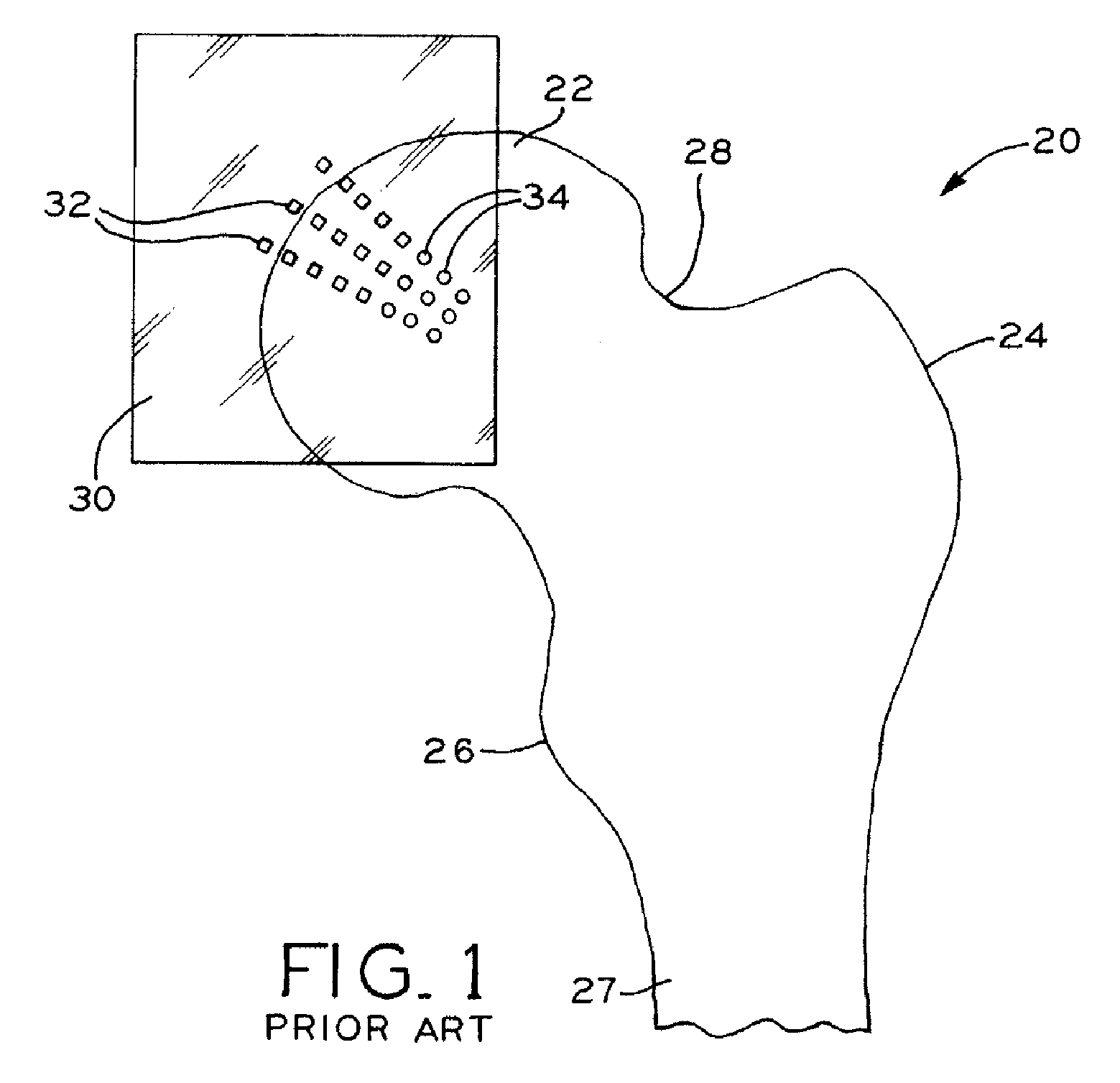
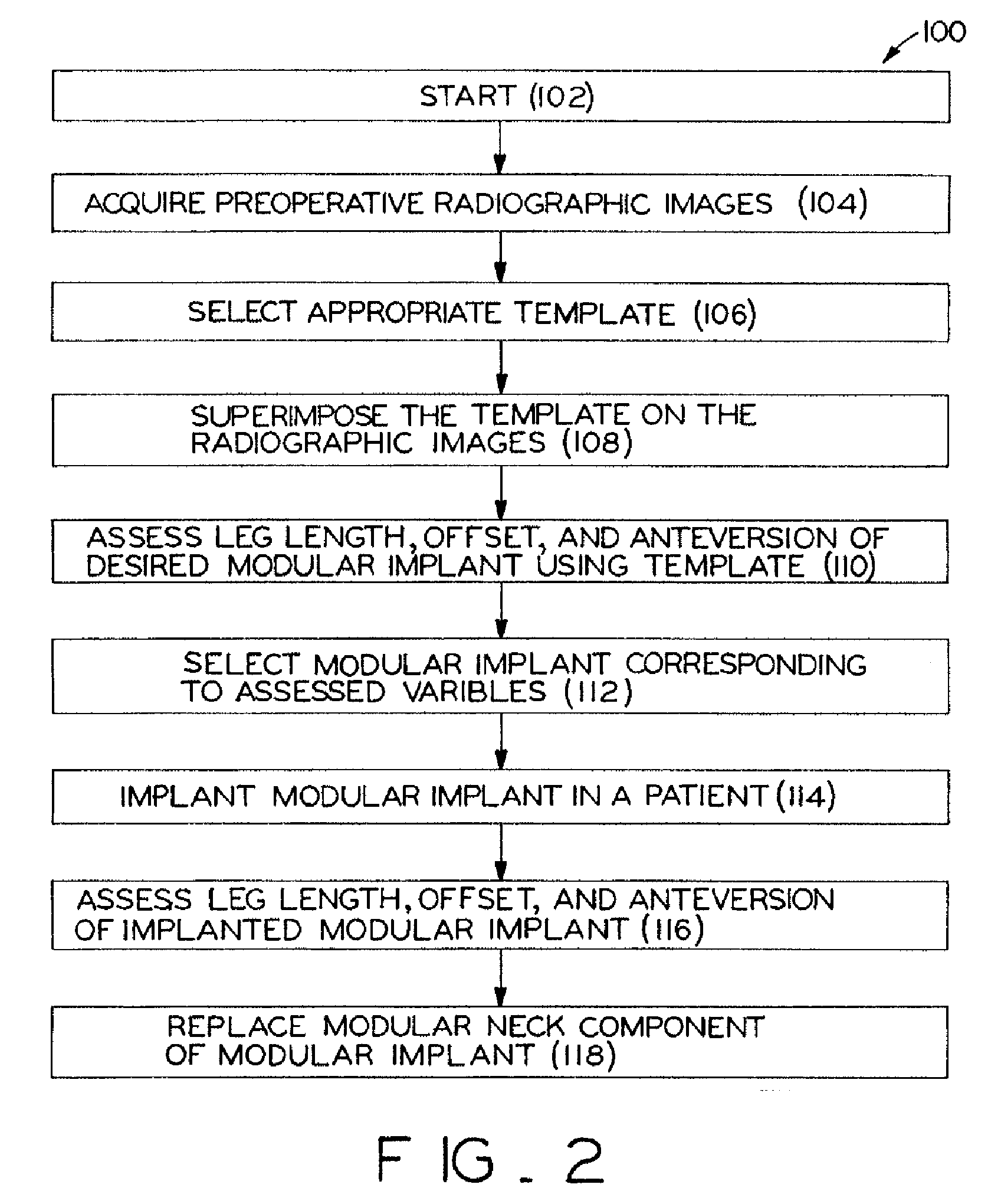
[0022]Referring to FIG. 2, a flow chart illustrating steps of method 100 is shown and includes several steps beginning with step 102. Step 102 includes preparing a patient (not shown) for the surgical procedure, e.g., collecting information and past medical history. In step 104, the surgeon or a surgeon's assistant will acquire at least one image of the appropriate portion of the hip region of the patient, e.g., at least a portion of the femur and the hip joint. The image may be a radiographic image such as an X-ray image or fluoroscopic image, for example, or, alternatively, a computed tomography (CT) image, a magnetic resonance image (MRI), or any other suitable image. Typical images for a hip replacement procedure may be taken along two different directions. For example, anterior / posterior (A / P) and lateral pelvic images may be taken of the hip joint.

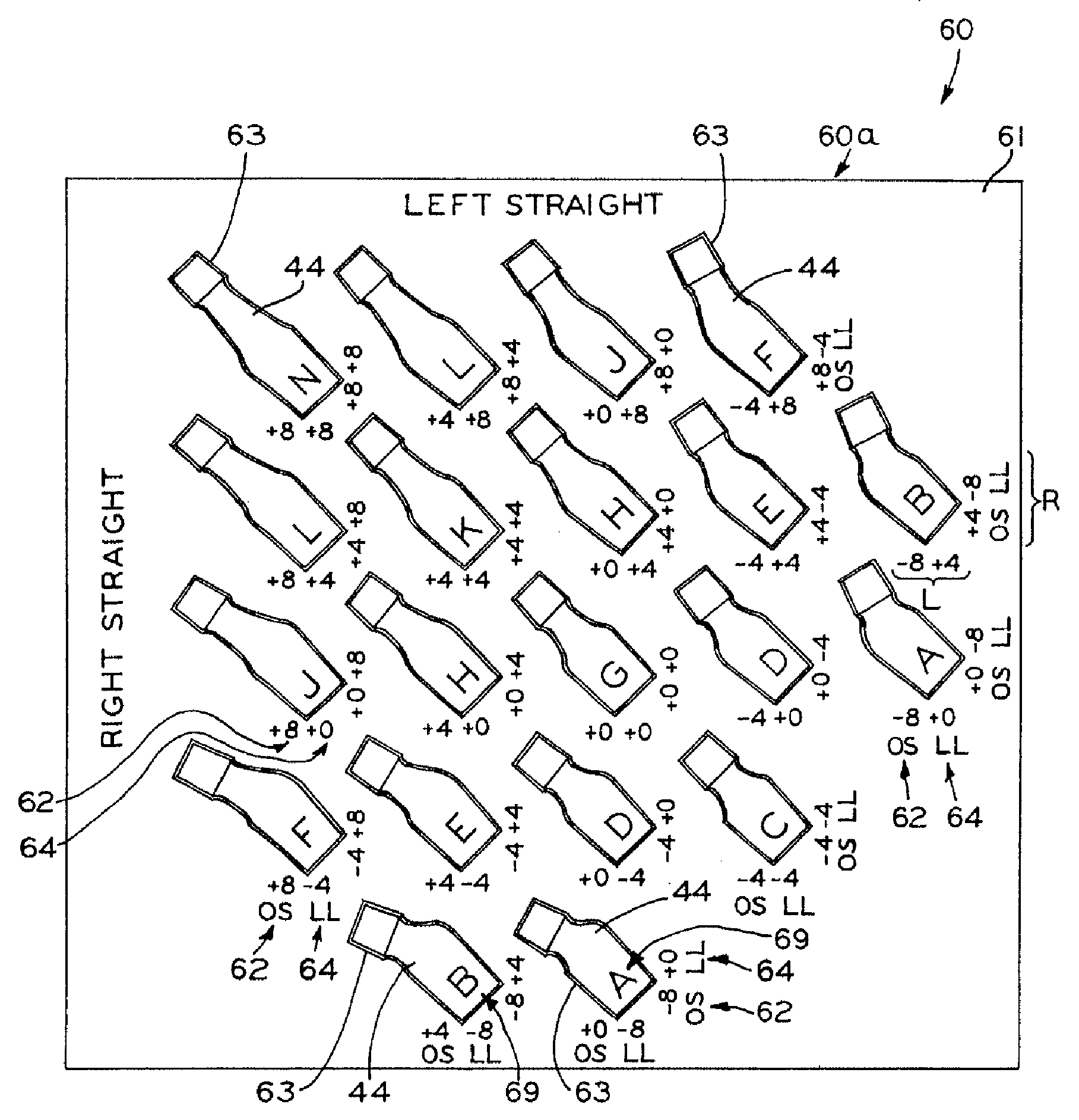
[0023]Referring now to FIG. 3, a template 50 is shown which may be used in conjunction with the images to preoperatively plan a sur...


PUM


Abstract

A case for modular neck components for hip implants. The case may include indicators based on independent variables associated with physical characteristics of the implant, including leg length, offset, and anteversion. During surgery, the surgeon may be confronted with a need to change a preoperatively-chosen modular neck. For example, the surgeon may desire a change in at least one of the variables, e.g., leg length, offset, and/or anteversion. The case allows the surgeon to quickly and easily select a different modular neck based on an evaluation of one of the variables without requiring reevaluation of the other variables. A method described herein may include preoperative planning in which a template including a grid coordinate system is used, which advantageously provides an intuitive system for the surgeon both preoperatively and during surgery.

Description

CROSS REFERENCE TO RELATED APPLICATIONS[0001]This application is a continuation-in-part of co-pending U.S. patent application Ser. No. 11 / 458,257, filed Jul. 18, 2006, entitled METHOD FOR SELECTING MODULAR IMPLANT COMPONENTS, assigned to the assignee of the present application, the disclosure of which is hereby expressly incorporated herein by reference.BACKGROUND[0002]1. Field of the Invention[0003]The present invention relates to modular components for prosthetic joints. More particularly, the present invention relates to a case for modular neck components for prosthetic hip joints.[0004]2. Description of the Related Art[0005]Orthopaedic prosthetic implants are commonly used to replace some or all of a patient's hip joint in order to restore the use of the hip joint, or to increase the use of the hip joint, following deterioration due to aging or illness, or injury due to trauma. In a hip replacement, or hip arthroplasty procedure, a femoral component is used to replace a portion ...

Claims


Application Information

Patent Timeline
Patent Type & Authority Applications(United States)
IPC IPC(8): A61F2/32
CPCA61B5/107A61F2250/0089A61B19/026A61B19/0271A61B2019/0278A61F2/0095A61F2/3609A61F2/38A61F2/40A61F2/46A61F2002/30332A61F2002/30604A61F2002/30616A61F2002/30708A61F2002/30714A61F2002/30948A61F2002/30963A61F2002/3611A61F2002/3625A61F2002/365A61F2002/3652A61F2002/4633A61F2220/0033A61F2250/0084A61B5/4528A61B50/30A61B50/33A61B2050/3008A61F2002/3071
Inventor MEULINK, STEVEN L.SCHLOTTERBACK, RYAN D.BANERJEE, BARISHVANKOSKI, STEPHEN J.
Owner ZIMMER INC
Why Eureka
Try Eureka