Electrically Powered Rail Propulsion Vehicle and Method

a technology of electric power rail and propulsion vehicle, which is applied in the direction of propulsion parts, gas pressure propulsion mounting, process and machine control, etc., can solve the problems of dual-mode locomotive, stalling, and inevitable “gapping”

Inactive Publication Date: 2008-01-24
ISE
View PDF21 Cites 53 Cited by
  • Summary
  • Abstract
  • Description
  • Claims
  • Application Information

AI Technical Summary

Benefits of technology

[0010] An aspect of the invention involves a method of bridging a gap in an external electrical power supply line without stalling, using an electrically powered rail propulsion vehicle. The method includes using an electrically powered rail propulsion vehicle to propel a train of cars, the electrically powered rail propulsion vehicle configured to run as an emission-free pure electric unit from the external traction power provided by an external electrical power supply line; determining if a gap in the external electrical power supply line condition occurs; and supplying electric power from one or more ultracapacitor packs to run the electrically powered rail propulsion vehicle if a gap condition is determined to occur. According to one embodiment, the continued flow of current through the electric drive motors now coming from the ultracapacitor packs allows the magnetic energy of the electric drive motor inductance to more slowly discharge as the ultracapacitor discharges. The net effect is that the ultracapacitor pack serves to suppress the “arc” that would otherwise occur. This is particularly effective when the ultracapacitor packs are in parallel with power pickups

Problems solved by technology

However, if the power pickup is from a third rail, the dual-mode locomotive has the major drawback that it is subject to stalling when it traverses conductor-rail gaps (i.e., when “gap jumping”).
Moreover, “gapping” is inevitable in any third rail system.
However, in the vicinity of a major interlocking, unlike overhead catenary systems, the inevitable discontinuity of the third rail can be an issue.
Under adverse conditions (for example when a 15 mph terminal speed restriction and an ascending grade are taken into account) however, gap stalling is a real concern.
However, they are of limited use for a locomotive because there is a reasonably lengthy pre-charge time before the main breaker re-closes and applies power to the traction motors.
Another approach to avoid gap stalling is where dual-mode locomotives are provided at opposite ends of a train of railcars. lacing locomotives on opposite ends of a train of cars may result in substantial additional and unnecessary expense to the operator.

Method used


Image

  • Electrically Powered Rail Propulsion Vehicle and Method
  • Electrically Powered Rail Propulsion Vehicle and Method
  • Electrically Powered Rail Propulsion Vehicle and Method

Examples


Embodiment Construction

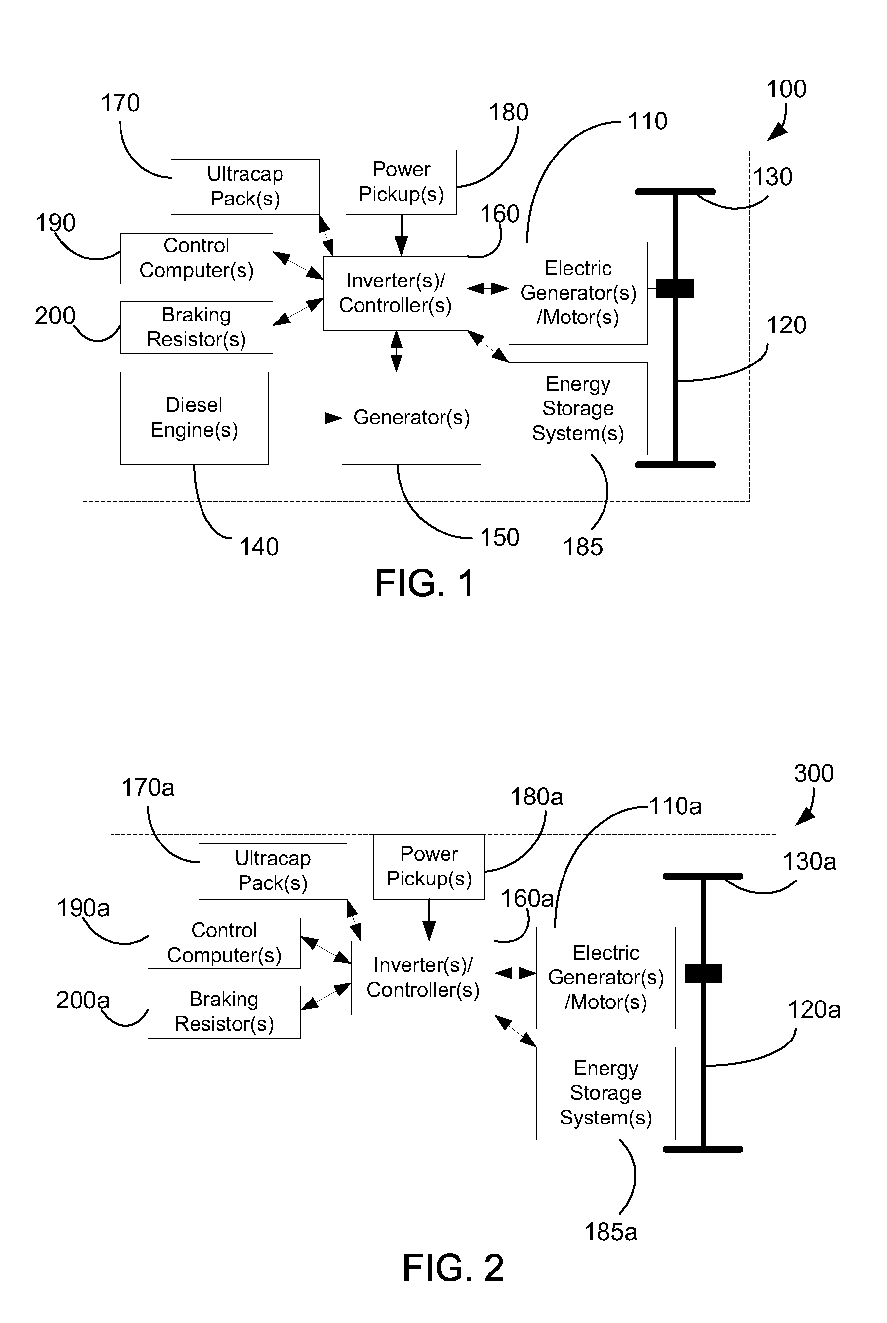
[0017] Embodiments of electrically powered rail propulsion vehicles incorporating systems and methods directed toward overcoming problems associated with “gap jumping” will be described. Examples of electrically powered rail propulsion vehicles include, but not by way of limitation, dual-mode locomotives, electric street cars, and electrically powered light rail commuter cars. As used herein, “gap jumping” refers to bridging the sections of a rail line where gaps, gaplets, or phase breaks exist in an external electrical power supply. Examples of an external electrical power supply include, but not by way of limitation, a third rail and an overhead catenary power system. Additionally, it is understood that certain aspects of the features claimed may be combined in a single unit, or separated into multiple units.

[0018] Referring to FIG. 1, depicted is a block diagram of an embodiment of a dual-mode locomotive 100 incorporating certain aspects of the invention, further described below...


PUM


Abstract

A method of bridging a gap in an external electrical power supply line without stalling using an electrically powered rail propulsion vehicle includes using an electrically powered rail propulsion vehicle to propel a consist, the electrically powered rail propulsion vehicle configured to run as an emission-free pure electric unit from the external electrical power supply line; determining if a gap in the external electrical power supply line condition occurs; and supplying electric power from one or more ultracapacitor packs to run the electrically powered rail propulsion vehicle if a gap condition is determined to occur.

Description

CROSS-REFERENCE AND RELATED APPLICATION [0001] This application is a continuation-in-part of U.S. patent application Ser. No. 11 / 467,038, filed Aug. 24, 2006, which is a continuation-in-part of U.S. patent application Ser. No. 11 / 420,064, filed May 24, 2006. This application claims the benefit of these prior applications, and these prior applications are incorporated by reference herein as though set forth in full.FIELD OF THE INVENTION [0002] The field of the invention relates to electrically powered rail propulsion vehicles such as dual-mode locomotives, electric street cars, and electrically powered light rail commuter cars. BACKGROUND OF INVENTION [0003] A dual-mode locomotive is capable of running as an emission-free pure electric unit from an external electric traction power source (e.g., a third rail) or, when in non-electrified territory, as a conventional diesel unit. However, if the power pickup is from a third rail, the dual-mode locomotive has the major drawback that it ...

Claims


Application Information

Patent Timeline
Patent Type & Authority Applications(United States)
IPC IPC(8): G05D1/00B61C3/00H02J7/00H02K7/02
CPCB60L7/06B60L7/14B60L7/22B60L9/00B60L2200/26B60L11/16B60L11/1803Y02T10/7005Y02T10/7022B60L11/005B60L50/30B60L50/40B60L50/51Y02T10/70
Inventor KINGHAM, JOHN R.BARTLEY, THOMAS L.KAUFMANN, PAUL E.
Owner ISE
Why Eureka
Try Eureka