Method and Apparatus for Urea Injection in an Exhaust Aftertreatment System

a technology of exhaust aftertreatment and urea injection, which is applied in the direction of mechanical equipment, engines, machines/engines, etc., can solve the problems of increasing nox emissions and the typical urea injection control system currently in use is not capable of controlling urea injection at very low flow ra

Active Publication Date: 2008-01-31
GM GLOBAL TECH OPERATIONS LLC
View PDF17 Cites 70 Cited by
  • Summary
  • Abstract
  • Description
  • Claims
  • Application Information

AI Technical Summary

Problems solved by technology

When an engine operates in a region lean of air / fuel stoichiometry, a resultant typically includes increased combustion temperatures, leading to increased NOx emissions.
Typical urea injection control systems currently in use are not capable of controlling urea injection at very low flow rates, which typically occur at engine idle conditions and when a vehicle is decelerating, i.e. conditions when the engine is producing very low engine-out NOx emissions.
The catalyst is able to continue NOx reduction when the urea injection control system is not capable of controlled dosing, i.e., supplying a controlled amount of urea.

Method used


Image

  • Method and Apparatus for Urea Injection in an Exhaust Aftertreatment System
  • Method and Apparatus for Urea Injection in an Exhaust Aftertreatment System
  • Method and Apparatus for Urea Injection in an Exhaust Aftertreatment System

Examples


Embodiment Construction

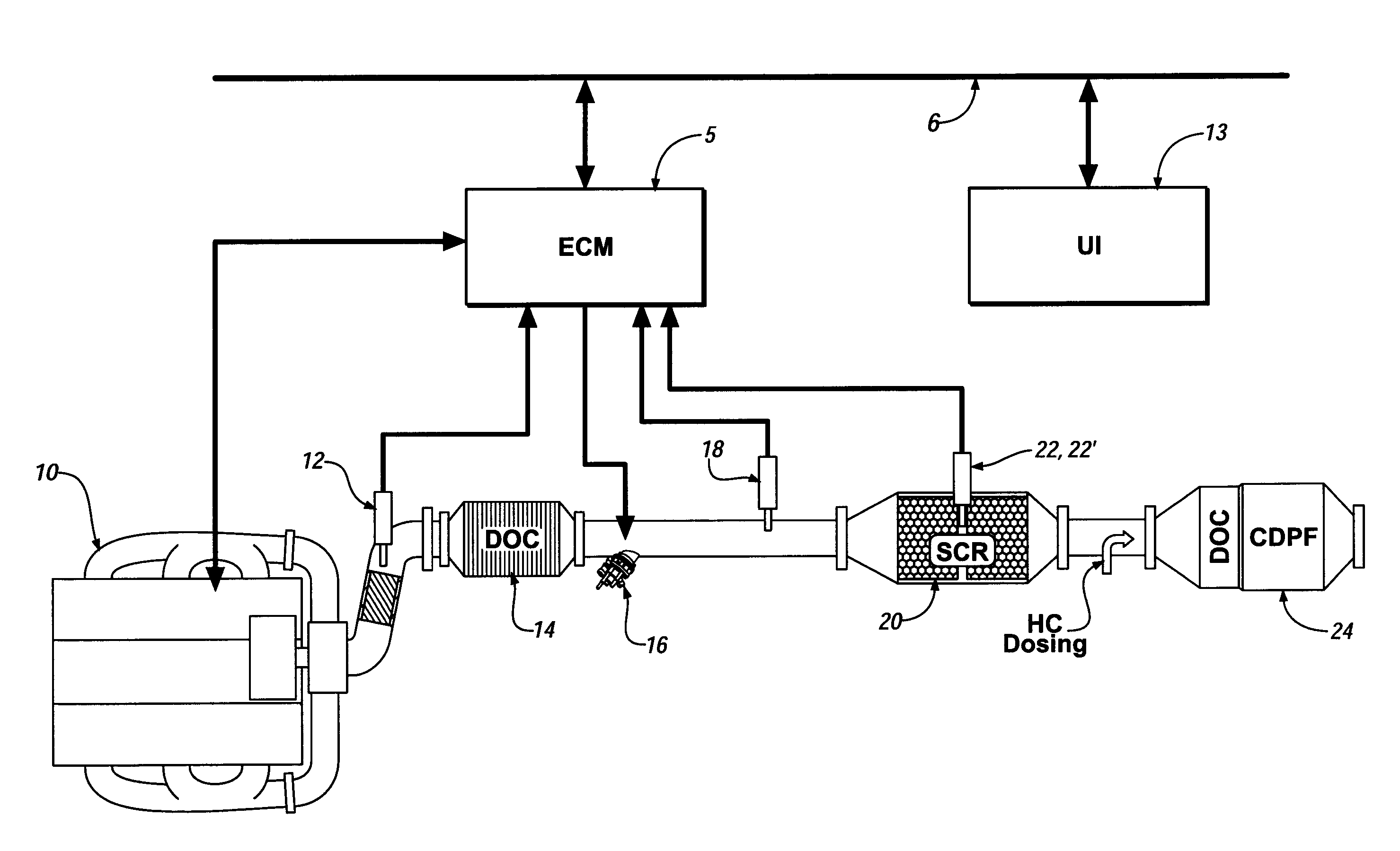
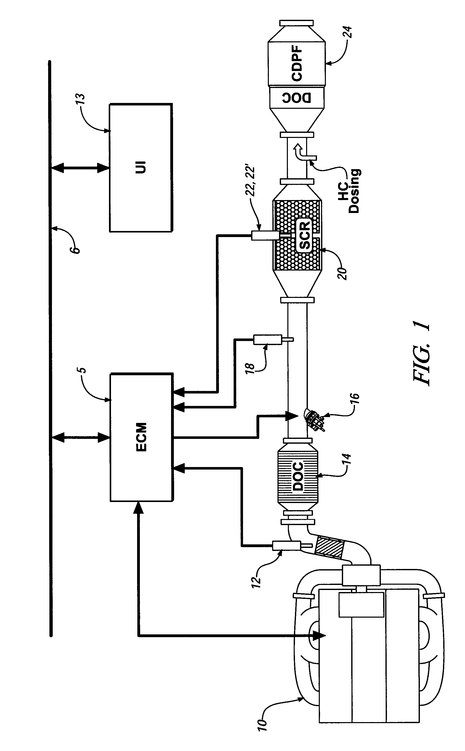
[0013]Referring now to the drawings, wherein the showings are for the purpose of illustrating the invention only and not for the purpose of limiting the same, FIG. 1 shows a schematic diagram of an internal combustion engine, exhaust aftertreatment system, and control system which has been constructed in accordance with an embodiment of the present invention.

[0014]The exemplary engine and control system comprises a four-cycle internal combustion engine 10 and electronic engine control module (‘ECM’) 5. The exemplary engine comprises a diesel compression-ignition engine having an operating regime that is primarily lean of stoichiometry. Alternatively, the engine may comprise an engine using any one of a number of engine control strategies which operate lean of stoichiometry, e.g. homogeneous-charge compression-ignition engines, and lean-bum spark-ignition engines. The exemplary engine 10 includes a plurality of reciprocating pistons attached to a crankshaft, which is operably attache...


PUM


Abstract

An exhaust aftertreatment system and control system is provided, including a urea injecting device, a selective catalyst reduction device, and, a sensing device operative to monitor a forward portion of the selective catalyst reduction device. The sensing device can comprise a NOx sensor, and alternatively, an ammonia sensor. A control module adapted to monitor signal inputs from the engine, the NOx sensing system, the temperature sensing system, and the sensing device operative to monitor a forward portion of the selective catalyst reduction device; and, adapted to control operation of the urea injecting device.

Description

TECHNICAL FIELD[0001]This invention pertains generally to exhaust aftertreatment systems for internal combustion engines.BACKGROUND OF THE INVENTION[0002]Manufacturers of internal combustion engines are continually developing new engine control strategies to satisfy customer demands and meet various regulations. One such engine control strategy comprises operating an engine at an air / fuel ratio that is lean of stoichiometry to improve fuel economy and reduce greenhouse gas emissions. Such engines include both compression-ignition (diesel) and lean-burn spark-ignition engines. When an engine operates in a region lean of air / fuel stoichiometry, a resultant typically includes increased combustion temperatures, leading to increased NOx emissions.[0003]One proposed type exhaust aftertreatment system and control strategy for managing and reducing NOx emissions includes injection of urea into an exhaust gas feedstream upstream of a selective catalytic reduction (‘SCR’) catalytic device to ...

Claims


Application Information

Patent Timeline
Patent Type & Authority Applications(United States)
IPC IPC(8): F01N3/00
CPCF01N3/035F01N3/208F01N11/002F01N13/008F01N2560/021F01N2560/026F01N13/0093F01N2610/02Y02T10/47Y02T10/24F01N13/009F01N13/0097F01N2570/18Y02T10/12Y02T10/40
Inventor VIOLA, MICHAEL B.BROWN, DAVID B.PARATORE, MICHAEL J.
Owner GM GLOBAL TECH OPERATIONS LLC
Why Eureka
Try Eureka