Dynamic gain adjustment method based on brightness and apparatus thereof

Active Publication Date: 2008-01-31
SAMSUNG ELECTRONICS CO LTD
6 Cites 18 Cited by

AI-Extracted Technical Summary

Problems solved by technology

This may cause unwanted results, suc...

Method used

[0058]Accordingly, the gain can be dynamically adjusted when the APL of the input video signal is high...

Benefits of technology

[0012]The present invention provides a dynamic gain adjustment method and apparatus based on brightness, which can dynamically vary a gain that is appl...

Abstract

A dynamic gain adjustment method and apparatus based on brightness are provided. The dynamic gain adjustment method and apparatus amplify or attenuate high frequency components of an input video signal by dynamically varying a gain that is applied to a peaking algorithm block for picture quality improvement in a video processing device, such as a digital television, based on an average picture level (APL) of the input video signal. The gain can be dynamically adjusted when the APL of the input video signal is high or low, and thus saturation of the video signal during the operation of the peaking block can be prevented.

Application Domain

Technology Topic

Image

  • Dynamic gain adjustment method based on brightness and apparatus thereof
  • Dynamic gain adjustment method based on brightness and apparatus thereof
  • Dynamic gain adjustment method based on brightness and apparatus thereof

Examples

  • Experimental program(1)

Example

[0028]Throughout the drawings, like reference numerals will be understood to refer to like parts, components, and structures.
DETAILED DESCRIPTION OF EXEMPLARY EMBODIMENTS OF THE INVENTION
[0029]The matters defined in the description, such as a detailed construction and elements, are provided to assist in a comprehensive understanding of embodiments of the invention, and are merely exemplary. Accordingly, those of ordinary skill in the art will recognize that various changes and modifications of the exemplary embodiments described herein can be made without departing from the scope and spirit of the invention. Also, descriptions of well-known functions and constructions are omitted for clarity and conciseness.
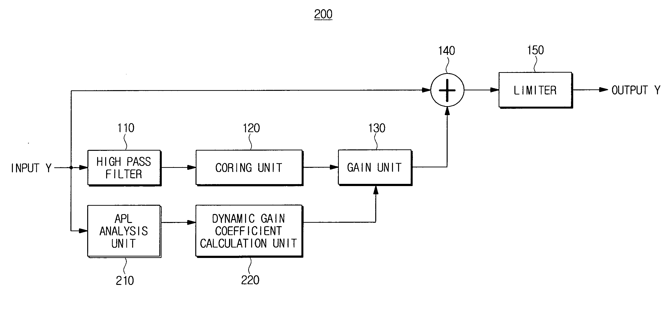
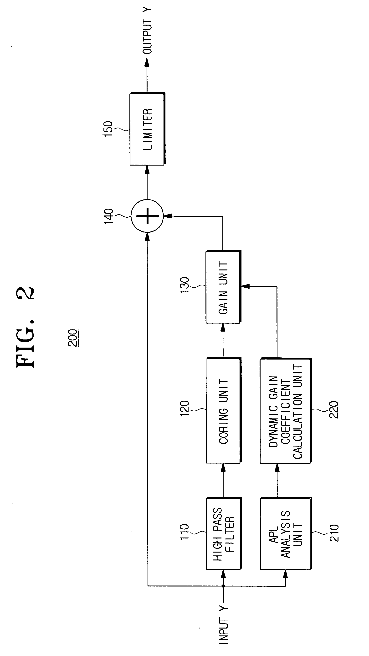
[0030]FIG. 2 is a block diagram illustrating the construction of a dynamic gain adjustment based on brightness according to an exemplary embodiment of the present invention.
[0031]The dynamic gain adjustment apparatus 200 comprises an HPF 110, a coring unit 120, a gain unit 130, a mixer 140, a limiter 150, an APL analysis unit 210, and a dynamic gain coefficient calculation unit 220.
[0032]The HPF 110 separates high frequency components from an input video signal.
[0033]The coring unit 120 removes components which are less than a specified size from the high frequency components of the input video signal. The coring unit 120 is mainly used to remove noise.
[0034]The gain unit 130 amplifies or attenuates the high frequency components of the video signal applied from the coring unit 120.
[0035]The mixer 140 mixes the video signal, of which the high frequency components have been amplified or attenuated, with the input video signal.
[0036]The limiter 150 limits a peaked part of the mixed video signal.
[0037]The APL analysis unit 210 calculates an APL value of the input video signal in the unit of a frame. For example, if a frame is composed of 512 pixels, the APL analysis unit 210 calculates the APL value by summing up the picture values of the 512 pixels that constitute one frame, and then dividing the summed value by 512.
[0038]The dynamic gain coefficient calculation unit 220 calculates a gain coefficient having the characteristic as illustrated in FIG. 4, in accordance with the APL value applied from the APL analysis unit 210, and transfers the calculated gain coefficient to the gain unit 130.
[0039]It can be seen from FIG. 4 that the gain coefficient calculated by the dynamic gain coefficient calculation unit 220 has a very small value if the picture is very dark because the APL value is smaller than normal, or the picture is very bright because the APL value is larger than normal. Also, as illustrated in FIG. 4, if the picture has an APL value of ‘a’ and a gain of ‘g’, a preset gain coefficient is applied to the video signal without modification.
[0040]FIG. 3 is a flowchart illustrating a dynamic gain adjustment method based on brightness according to an exemplary embodiment of the present invention.
[0041]The dynamic gain adjustment apparatus can be applied to a digital TV that processes and outputs an input video signal. The dynamic gain adjustment apparatus can also be applied to all video processing devices that have peaking algorithm blocks.
[0042]In addition, the dynamic gain adjustment apparatus can be applied to a peaking algorithm block used for picture quality improvement when a video signal input to the digital TV is processed through a video decoder, a deinterlacer, or a scaler.
[0043]First, a video signal is inputted to a receiving unit of the dynamic gain adjustment apparatus according to an exemplary embodiment of the present invention (S302).
[0044]The input video signal is also applied to the HPF 110 and the APL analysis unit 210.
[0045]The APL analysis unit 210 calculates the APL of the input video signal in the unit of a frame, and transfers the calculated APL to the dynamic gain coefficient calculation unit 220 (S304).
[0046]For example, if a frame is composed of 1024×680 pixels, the APL analysis unit 210 calculates the APL value by summing up picture values of the respective pixels, and then dividing the summed value by 1024×680.
[0047]The dynamic gain coefficient calculation unit 220 calculates a dynamic gain coefficient having the characteristic as illustrated in FIG. 4, based on the APL value transferred from the APL analysis unit 210 (S306).
[0048]With reference to FIG. 4, the dynamic gain coefficient calculation unit 220 calculates a slope value ‘α’, based on which a gain value ‘g’ is calculated by the gain unit 130. Here, the slope value corresponds to the dynamic gain coefficient.
[0049]Specifically, the dynamic gain coefficient calculation unit 220 calculates the dynamic gain coefficient such that the gain value decreases when the APL value is smaller than a general APL value ‘a’, as shown in FIG. 4. In the same manner, the dynamic gain coefficient calculation unit 220 calculates the dynamic gain coefficient such that the gain value decreases when the APL value is larger than the general APL value ‘a’.
[0050]Also, the dynamic gain coefficient calculation unit 220 calculates the dynamic gain coefficient such that a preset gain value ‘g’ is used when the APL value is within a range of normal APL values near ‘a’, as illustrated in FIG. 4.
[0051]The dynamic gain coefficient calculation unit 220 then transfers the calculated dynamic gain coefficient to the gain unit 130 (S308).
[0052]The HPF 110 separates high frequency components from the input video signal, and the coring unit 120 removes components which are less than a specified size from the high frequency components of the input video signal. The gain unit 130 amplifies or attenuates the high frequency components of the video signal applied from the coring unit 120 in accordance with the dynamic gain coefficient applied from the dynamic gain coefficient calculation unit 220.
[0053]The gain unit 130 amplifies or attenuates the high frequency components by adjusting the gain in accordance with the characteristic of FIG. 4, which is obtained through the dynamic gain coefficient applied from the dynamic gain coefficient calculation unit 220 (S310).
[0054]Accordingly, the dynamic gain adjustment apparatus can dynamically adjust the gain in both cases where the APL of the input video signal is high and low.
[0055]The dynamic gain adjustment apparatus 200, including the APL analysis unit 210 and the dynamic gain coefficient calculation unit 220, can be applied to the horizontal or vertical peaking of a video processing device provided with a peaking algorithm block. Also, the apparatus 200 can be applied to all integrated circuits (IC) using the peaking function in the video processing device, such as a TV.
[0056]Exemplary embodiments of the present invention can be written as codes, instructions, or programs, and can be implemented in general-use devices that execute the codes, instructions, or programs using a computer-readable recording medium. Examples of the computer-readable recording medium comprise magnetic storage media, such as ROM, floppy disks, and hard disks; optical recording media, such as CD-ROMs and DVDs; and storage media. The computer-readable recording medium can also be distributed over network coupled computer systems so that the computer-readable code is stored and executed in a distributed fashion. Also, functional programs, codes, and code segments for accomplishing exemplary embodiments of the present invention can be easily construed by programmers skilled in the art to which the present invention pertains.
[0057]As described above, according to the dynamic gain adjustment method and apparatus based on brightness, the high frequency components of an input video signal can be amplified or attenuated by dynamically varying the gain that is applied to the peaking algorithm block for picture quality improvement in a video processing device, such as a digital TV, based on the APL of the input video signal.
[0058]Accordingly, the gain can be dynamically adjusted when the APL of the input video signal is high or low, and saturation of the video signal during the operation of the peaking block can be prevented.
[0059]In addition, by applying the dynamic gain adjustment to all peaking blocks used for a picture quality improvement, a smooth peaking operation can be achieved through the gain adjustment based on the brightness.
[0060]The foregoing exemplary embodiments and advantages are merely exemplary and are not construed as limiting the present invention. The present teaching can be readily applied to other types of apparatuses. Also, the description of exemplary embodiments of the present invention is intended to be illustrative, and not to limit the scope of the claims. Many alternatives, modifications, and variations will be apparent to those skilled in the art.

PUM

no PUM

Description & Claims & Application Information

We can also present the details of the Description, Claims and Application information to help users get a comprehensive understanding of the technical details of the patent, such as background art, summary of invention, brief description of drawings, description of embodiments, and other original content. On the other hand, users can also determine the specific scope of protection of the technology through the list of claims; as well as understand the changes in the life cycle of the technology with the presentation of the patent timeline. Login to view more.

Similar technology patents

Oil-based ink composition for ink-jet recording

InactiveCN101225268AImprove picture qualityExcellent image fixationInksPrintingEmulsionDiol
Owner:SEIKO EPSON CORP

Classification and recommendation of technical efficacy words

Why Eureka
Try Eureka