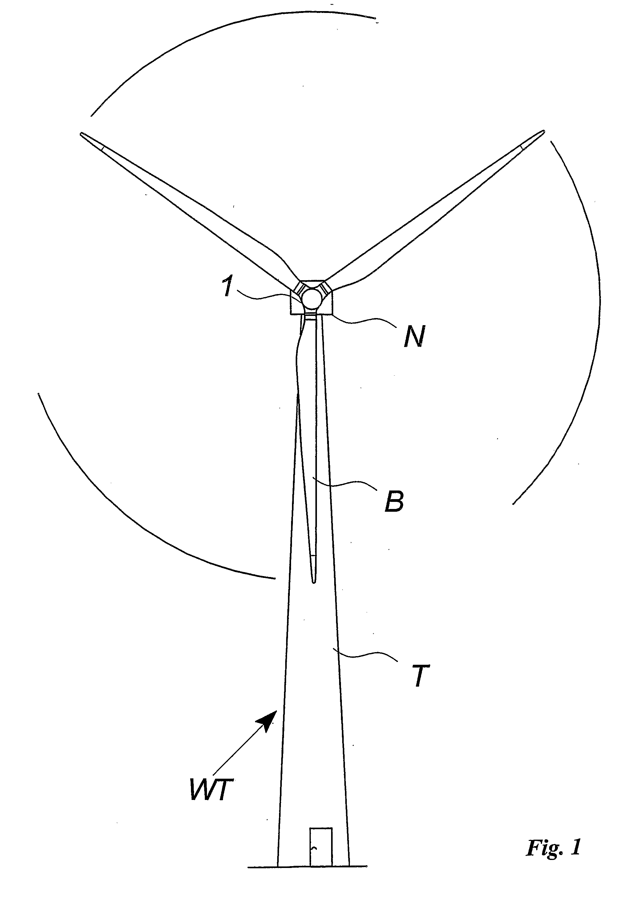
[0013] Thus, the present invention relates to a drive assembly for a wind turbine comprising a rotor hub, which is intended to support the wind turbine blades, a supporting structure, such as a wind turbine nacelle arranged on top of a
tower with a
yaw bearing to allow for a rotation of the supporting structure about a vertical
yaw axis, a planetary type gear transmission unit comprising a sun gear, a ring gear with a toothed inner surface, and a planet carrier having a plurality of planet gears arranged thereon, wherein said ring gear preferably is non-rotatably secured to said supporting structure and the planet carrier is co-rotatingly secured to the rotor hub, a
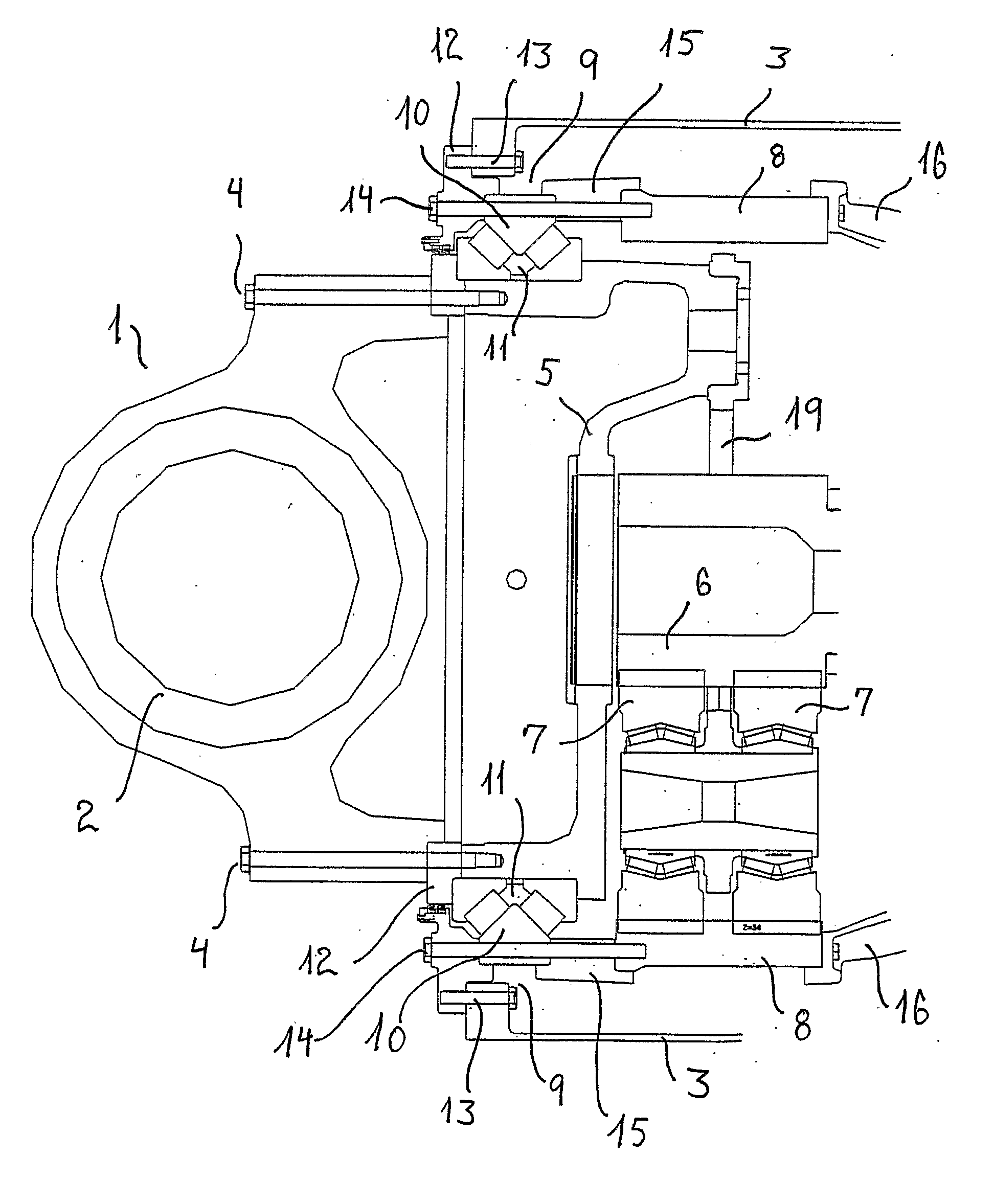
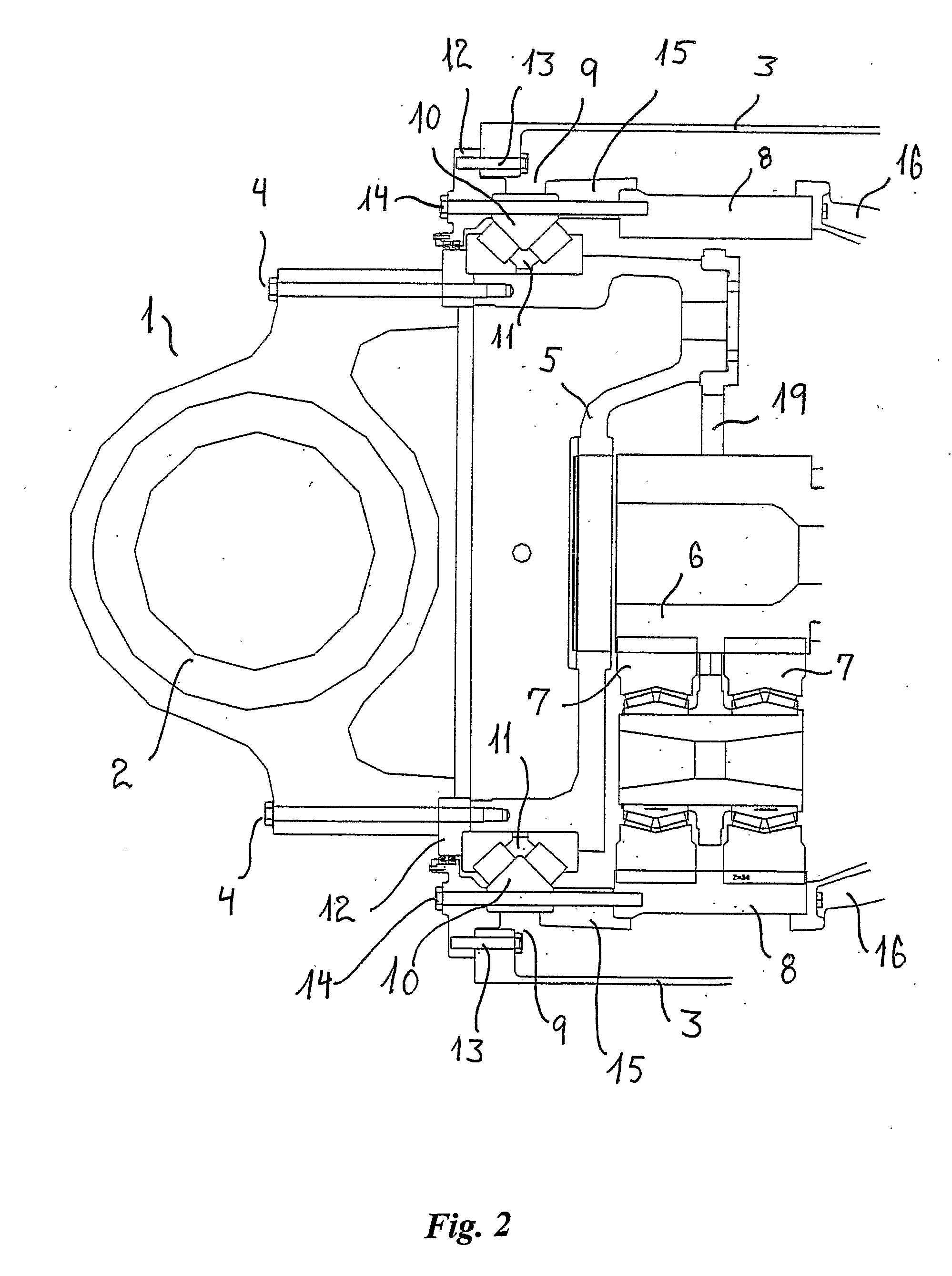
main bearing, such as a double taper bearing e.g. as disclosed in WO 03 / 014567, which rotatably supports the rotor hub relative to said supporting structure, the main bearing having a stationary part being non-rotatably secured to said supporting structure and a co-rotating part secured to the rotor hub. The drive assembly is exceptional in that the ring gear is flexibly arranged so as to allow for temporary radial displacements of the toothed inner surface of the ring gear during ordinary operation of the wind turbine so that the shape of the gear ring temporarily deviates from circular with the result that the radial forces between the plurality of planet gears and the ring gear are substantially equalized and extreme forces on one of the planet gears are avoided.
[0016] According to a second aspect of the present invention, which may advantageously be combined with the previously discussed aspect, a drive assembly for a wind turbine is provided comprising a rotor hub, supporting structure, a planetary type gear transmission unit comprising a sun gear, a ring gear with a toothed inner surface, and a planet carrier having a plurality of planet gears arranged thereon, said ring gear being non-rotatably secured to said supporting structure and the planet carrier being co-rotatingly secured to the rotor hub, a main bearing which rotatably supports the rotor hub relative to said supporting structure, the main bearing having a stationary part being non-rotatably secured to said supporting structure and a co-rotating part secured to the rotor hub, wherein the ring gear is flexibly arranged so as to allow for temporary angular displacements of the ring gear about the axis of rotation during ordinary operation of the wind turbine so as to dampen the transmission of drive torque peaks from the rotor hub to the sun gear. Thereby, positive as well as negative peaks or variations of the driving torque of the rotor, e.g. during wind gusts, may be taken up by the flexible securing and distributed over a longer period of time, which smoothens variations in the torque input to the sun wheel and the electrical generator and reduces peak stresses on the transmission unit. The maximum of said temporary angular displacements during ordinary operation of the wind turbine is preferably within the range of 0.2° to 6°, preferably within the range of 0.5° to 3°, and most preferred within the range of 1° to 3°.
[0017] The supporting structure comprises in a preferred embodiment a substantially annular
flange enclosing an axis of rotation of the hub, and the ring gear is secured to said annular
flange, whereby is understood that the ring gear is secured with securing means which are substantially evenly distributed around the periphery of the annular
flange. In yet another preferred embodiment, the stationary part of the main bearing as well as the ring gear are secured to said annular flange with a common securing structure, which allows for said temporary radial displacements of the toothed inner surface of the ring gear during operation of the wind turbine substantially without causing a corresponding deformation of the main bearing. Such common securing structure allow the supporting structure via the main bearing to take up transversal shear stresses and
bending moment forces from the rotor hub, whereas the torque from the rotor hub is transferred by the planet carrier to the supporting structure, wherein substantially all of the torque is transferred via the ring gear. The gearing of the planet type gear transmission is typically in the order of 1:100-1:200, which means that although most of the power from the rotor is transmitted to the electrical generators, only a fraction of the drive torque is transmitted to the electrical generator, whereas the remaining torque is transferred to the supporting structure via the ring gear.
[0018] The ring gear is preferably connected to the stationary part of the main bearing by means of an intermediate connector part of a flexible structure and having a first flange secured to the ring gear and a second flange secured to the stationary part of the main bearing. The intermediate flange may e.g. have openings defined therein and / or slots extending axially from the second flange and towards the first flange, so that the second flange is divided into a plurality of fingers connected to the first flange, or the slots may extend all through the first flange, so that the intermediate connector part consists of a plurality of arc-shaped pieces arranged along the annular flange of the supporting structure and connected to the ring gear, whereby the sufficient flexibility of the structure may be provided. The intermediate connector part extend in a preferred embodiment between 100 and 600 millimetres, preferably between 200 and 400 millimetres, in the axial direction, i.e. the direction parallel to the axis of rotation of the rotor hub, between the first and the second flange. In an alternative measure, the intermediate connector part extend preferably between 4 and 20% of the inner
diameter of the ring gear, preferably between 7 and 15% of the inner
diameter of the ring gear, in the axial direction between the first and the second flange.
[0019] In a preferred embodiments of the present invention, the intermediate connector part provides the flexibility of the support of the ring gear with respect to the temporary radial displacements as well as the temporary angular displacements, in particular in an embodiment, wherein the stationary part of the main bearing is fixed directly to an annular flange of the supporting structure and the ring gear is supported by the intermediate connector part fixed to the stationary part of the main bearing. Thereby, the stability of the shape of the stationary part of the main bearing is enhanced by the supporting structure, whereas the temporary displacements of the ring gear are taken up by the intermediate supporting structure.
[0023] The thickness of the ring gear outwards in the radial direction, i.e. normal to the toothed inner surface, may in a preferred embodiment be reduced to between 50 and 300 millimetres, preferably between 100 and 200 millimetres. In other measures, the thickness of the ring gear in the radial direction may be reduced to between 2 and 10% of the inner
diameter of the ring gear, preferably between 4 and 8% of the inner diameter of the ring gear, which means that the
mass of the ring gear may be substantially reduced as compared to other configurations of such drive assembly. The reduction in thickness is due to the allowed flexibility of the ring gear as compared to the known constructions, where deviations from the original circular shape of the ring gear are unacceptable, as they would cause deviations of the shape of the main bearing as well.

