
Interventional medical device system having an elongation retarding portion and method of using the same

Active Publication Date: 2008-01-31
CODMAN & SHURTLEFF INC
View PDF36 Cites 24 Cited by
  • Summary
  • Abstract
  • Description
  • Claims
  • Application Information

AI Technical Summary

Benefits of technology

[0012]To incorporate systems according to the preceding description into an implant delivery device, an actuation member is connected to the proximal portion, and an implantable medical device is associated with a deployment end of the actuation member. Movement of the proximal portion of the system away from the distal portion disengages the implantable device at a target location within the vasculature. The bridge member retards axial extension of the turns for improved control when releasing the implantable device.

Problems solved by technology

Due to the delicate tissue surrounding intracranial blood vessels, especially for example brain tissue, it is very difficult and often risky to perform surgical procedures to treat defects of the intracranial blood vessels.
Some of the problems that have been associated with these procedures relate to the accuracy of coil placement.
One drawback to using this type of system is the potential risk of melted adhesives contaminating the blood stream.
One drawback is that connecting the resistance heating coil to the power source requires running multiple wires through the pusher member.
Additionally, the electrical current traveling through the wires may create stray electromagnetic fields that have the potential to interfere with other surgical and monitoring equipment.
This type of ball and socket connection is rigid and causes the catheter to be stiff, making it difficult to guide the catheter through the vasculature of the body.
Further, the above-identified delivery systems typically require electronic equipment powered by a power source.
If the electronic equipment is defective or the power source fails, the procedure may be prolonged while the equipment is repaired or replaced.
Prolonging the procedure may expose the patient to additional risk.
This tends to increase the time and complexity of releasing the implantable device, as well as increasing the component and packaging costs.

Method used


Image

  • Interventional medical device system having an elongation retarding portion and method of using the same
  • Interventional medical device system having an elongation retarding portion and method of using the same
  • Interventional medical device system having an elongation retarding portion and method of using the same

Examples


Embodiment Construction

[0019]As required, detailed embodiments of the present invention are disclosed herein; however, it is to be understood that the disclosed embodiments are merely exemplary of the invention, which may be embodied in various forms. Therefore, specific details disclosed herein are not to be interpreted as limiting, but merely as a basis for the claims and as a representative basis for teaching one skilled in the art to variously employ the present invention in virtually any appropriate manner.

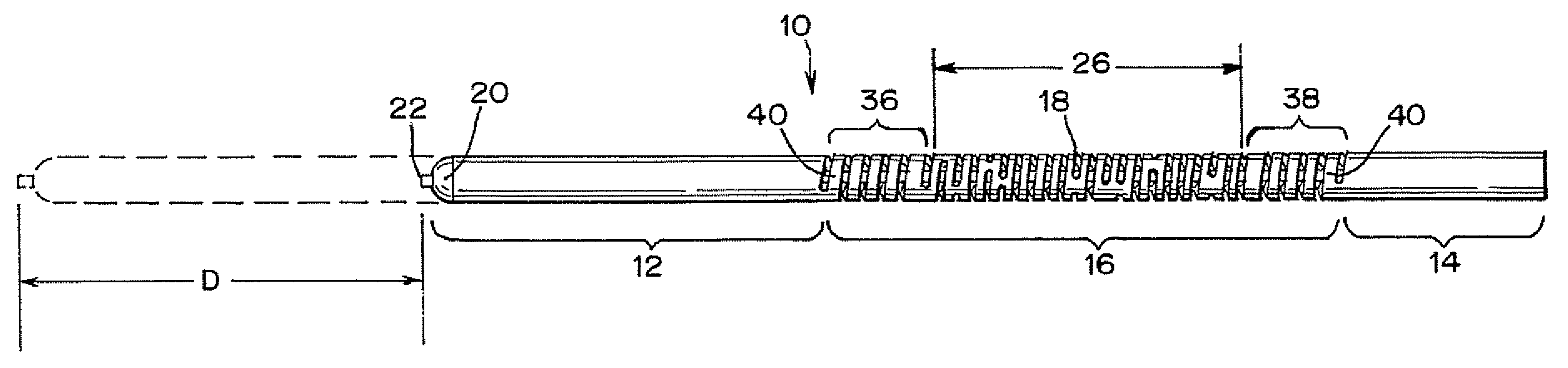
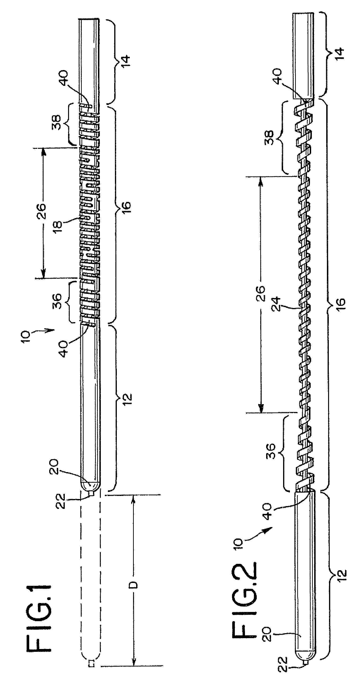
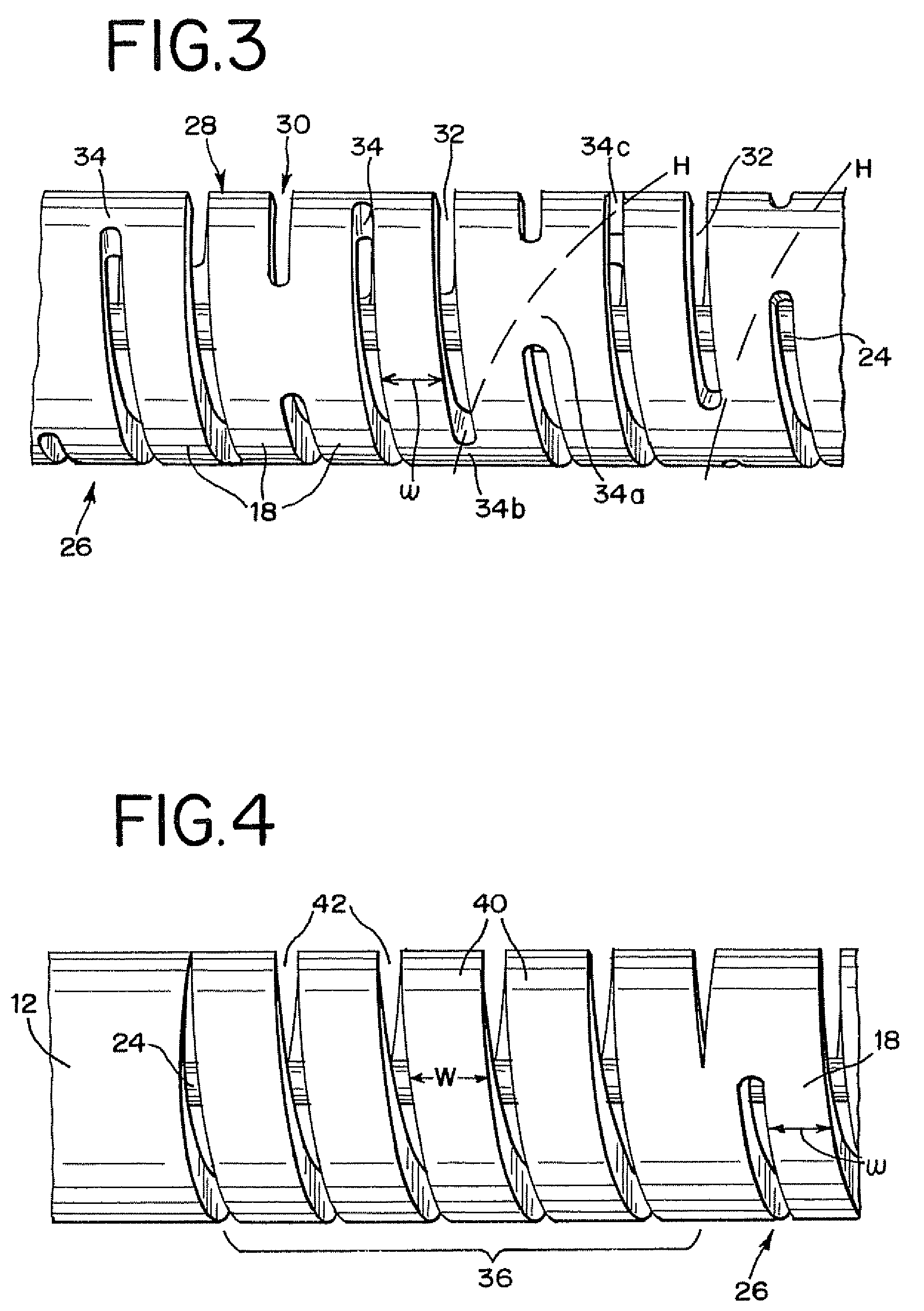
[0020]FIGS. 1 and 2 illustrate a generally hollow or tubular structure according to the present invention. When used herein, the terms “tubular” and “tube” are to be construed broadly and are not limited to a structure that is a right cylinder or strictly circumferential in cross-section or of a uniform cross-section throughout its length. For example, the tubular device or system is generally designated at 10 and shown as a substantially right cylindrical structure. However, the tubular system may...


PUM


Abstract

An interventional medical device system operable while within a body vessel is provided with a generally hollow tubular proximal portion, distal portion, and intermediate portion. The proximal portion and at least part of the distal portion remains outside of the body in use, with the remainder of the distal portion positioned within the body. The intermediate portion includes a spiral ribbon having adjacent turns, with at least one frangible bridge member between two adjacent turns. The proximal and distal portions are movable away from each other by elongating the spiral ribbon and, eventually, breaking the frangible bridge member. According to a method of using such a system to deploy an implantable medical device, such as an embolic coil, an actuation member is moved proximally with the proximal portion to disengage a bond or joint between the actuation member and the implantable medical device.

Description

FIELD OF THE INVENTION[0001]This invention generally relates to interventional medical device systems that are navigable through body vessels of a human subject. More particularly, this invention relates to tubular devices having a frangible elongation retarding feature and methods of using the same.DESCRIPTION OF RELATED ART[0002]The use of catheter delivery systems for positioning and deploying therapeutic devices, such as dilation balloons, stents and embolic coils, in the vasculature of the human body has become a standard procedure for treating vascular diseases. It has been found that such devices are particularly useful in treating areas where traditional operational procedures are impossible or pose a great risk to the patient, for example in the treatment of intracranial aneurysms. Due to the delicate tissue surrounding intracranial blood vessels, especially for example brain tissue, it is very difficult and often risky to perform surgical procedures to treat defects of the...

Claims


Application Information

Patent Timeline
IPC IPC(8): A61F2/02
CPCA61B17/12022A61B2017/12054A61B2019/307A61B2090/037
Inventor MITELBERG, VLADIMIRTHINNES, JOHN H.BALGOBIN, KEITHSOWERS, WILLIAM W.
Owner CODMAN & SHURTLEFF INC
Features
  • Generate Ideas
  • Intellectual Property
  • Life Sciences
  • Materials
  • Tech Scout
  • Unparalleled Data Quality
  • Higher Quality Content
  • 60% Fewer Hallucinations
Learn More