Simulated installation and operation of a diagnostic imaging device at a remote location

a diagnostic imaging and remote location technology, applied in the field of installation simulation of medical image diagnostic devices, can solve problems such as difficult to grasp operation feeling, easy psychological resistance of customers, and troublesome customers

Inactive Publication Date: 2008-01-31
GE HEALTHCARE JAPAN CORP
View PDF7 Cites 11 Cited by
  • Summary
  • Abstract
  • Description
  • Claims
  • Application Information

AI Technical Summary

Benefits of technology

[0007] Therefore, a first object of the present invention is to provide an installation simulation method which can automatically display an installing image of a medical image diagnostic device, system, program, and a recording medium recording the same.
[0008] A second object of the present invention is to provide an operation simulation method which can experience in a simulated manner the operation of a medical image diagnostic device, system, program, and a recording medium recording the same.
[0009] A third object of the present invention is to provide an imaging simulation method which can experience in a simulated manner the imaging of a medical image diagnostic device, system, program, and a recording medium recording the same.

Problems solved by technology

As in the related art, it is troublesome for the customer to check the size of the medical image diagnostic device to examine whether it can be installed into the imaging room or not.
In addition, when the customer asks the Vendor side to create an installing image each time, considering the effort of the Vendor side and the complicated personal procedure, the customer easily has a psychological feeling of resistance.
Further, the construction or features of the medical image diagnostic device can be understood to some degree on the home page, but the operation feeling is difficult to grasp.
Furthermore, it is difficult to grasp the procedure for setting the imaging conditions of the medical image diagnostic device and what image can be obtained by imaging.

Method used


Image

  • Simulated installation and operation of a diagnostic imaging device at a remote location
  • Simulated installation and operation of a diagnostic imaging device at a remote location
  • Simulated installation and operation of a diagnostic imaging device at a remote location

Examples


first embodiment

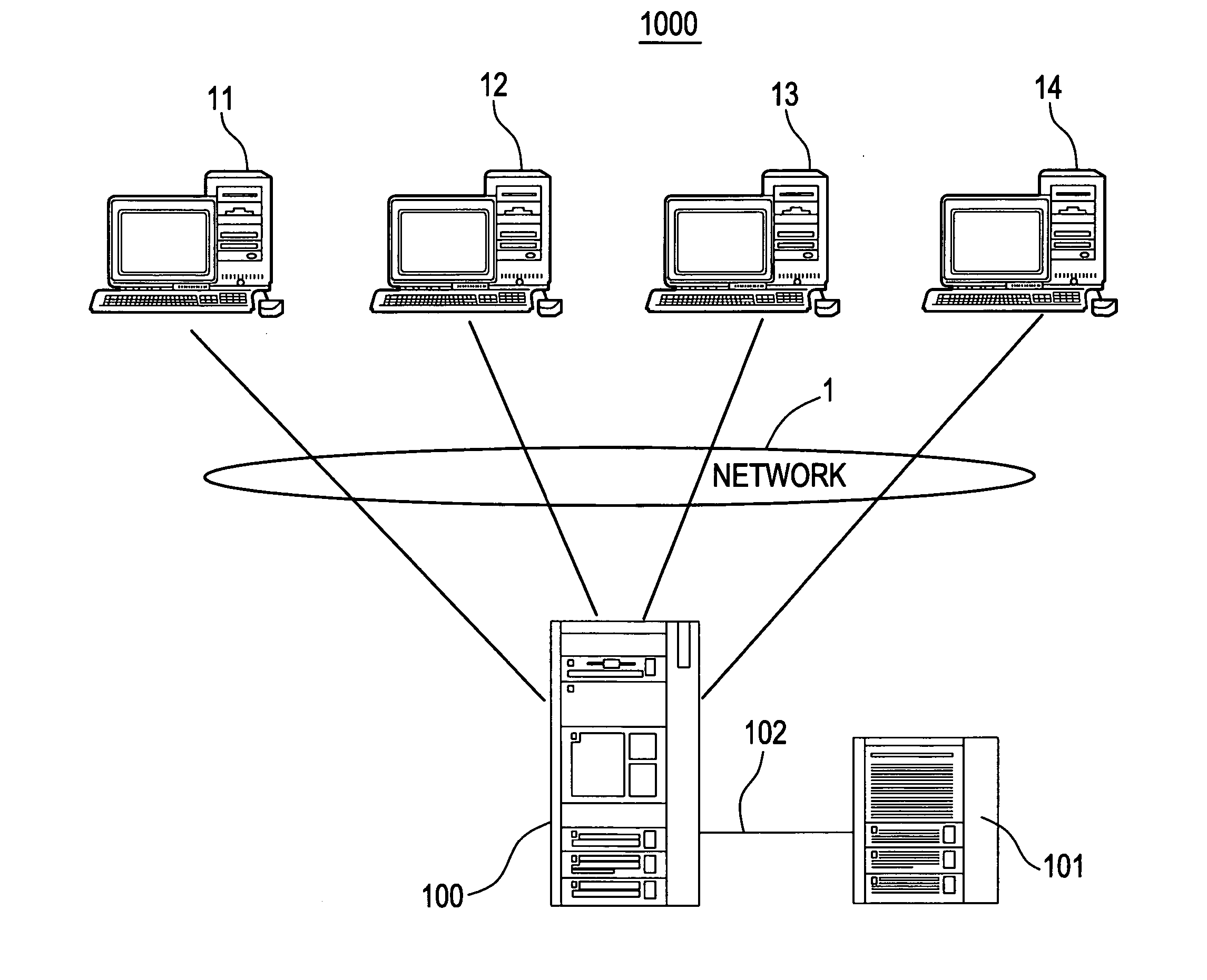
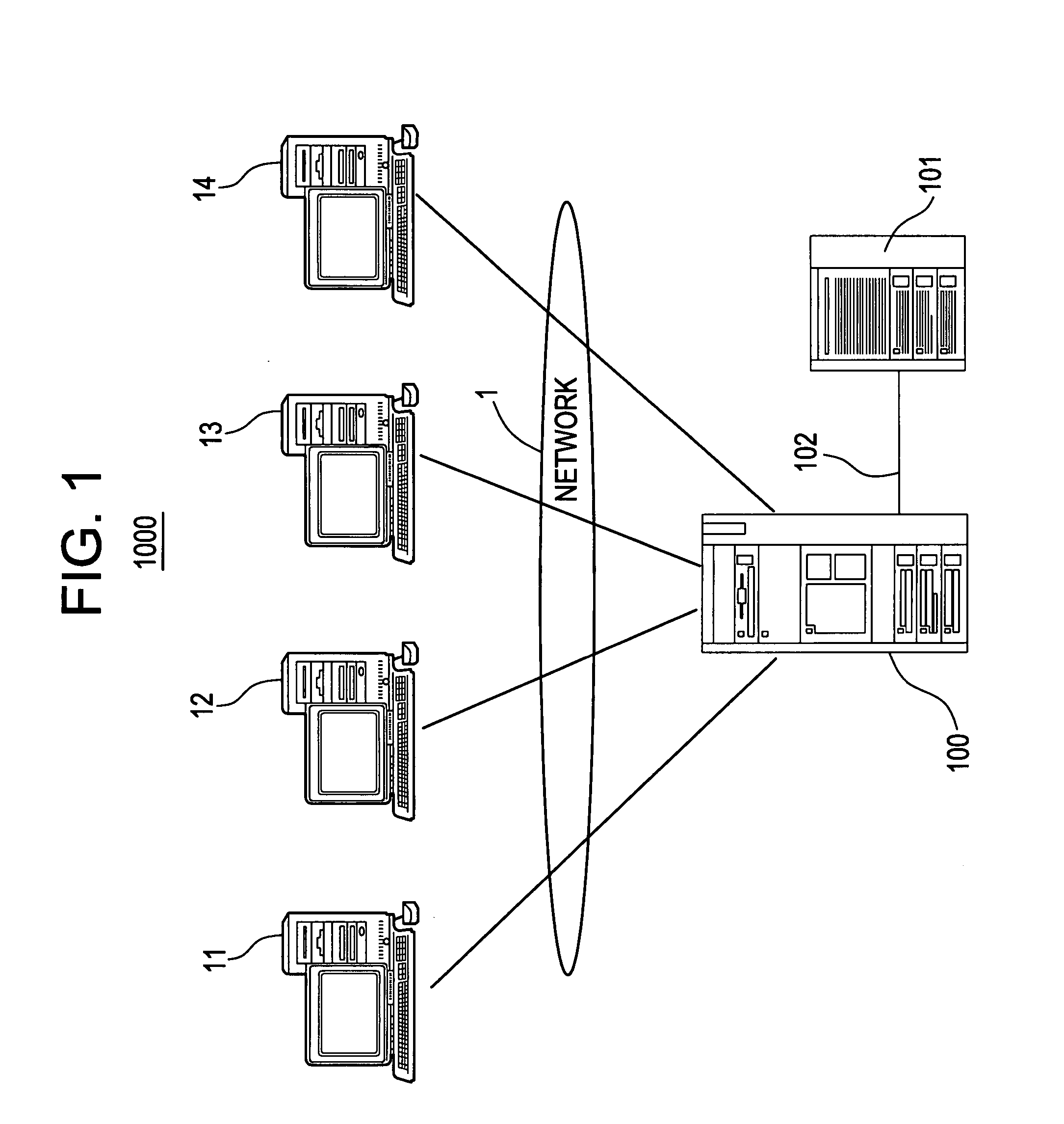
[0069]FIG. 1 is a block diagram showing an installation simulation system 1000 of a medical image diagnostic device according to a first embodiment of the present invention.

[0070] The installation simulation system 1000 has a network 1 such as Internet, LAN (Local Area Network), and WAN (Wide Area Network), customer side terminals 11, 12, 13 and 14 connected to the network 1 (which may be located in the same or different place), a host server device 100, and an arithmetic unit 101. The host server device 100 is connected to the arithmetic unit 101 through a communication line 102 such as LAN. The customer side terminals 11 to 14 are, for example, personal computers installing Web Browser. As the Web Browser, Internet Explorer (manufactured by Microsoft Corporation) and Netscape Navigator (manufactured by Netscape Communications Corporation) are widespread.

[0071] When the network 1 is Internet, a large number of terminals other than the customer side terminals 11 to 14 are also con...

second embodiment

[0106]FIG. 9 is a block diagram of a host server device 200 and an arithmetic unit 201 of an operation / imaging simulation system 2000 of a medical image diagnostic device according to a second embodiment of the present invention. The block diagram of the entire operation / imaging simulation system 2000 is similar to that of the installation simulation system 1000 of FIG. 1, and the illustration thereof is omitted.

[0107] The host server device 200 has a communication part 10A, an input part 10B, an output part 10C, an operation simulation Web Page storing part 20D for storing an operation simulation Web Page browsed by a customer, and an imaging simulation Web Page storing part 20E for storing an imaging simulation Web Page browsed by a customer, and is operated under control of a Web Page manage program.

[0108] The arithmetic unit 201 has a connection part 11A, an operation replay image generation part 21B for generating an image replaying the operation when the medical image diagno...

third embodiment

[0139]FIG. 17 is a block diagram showing a notebook computer 300 and a CD-ROM (Compact Disk-Read Only Memory) 301 according to a third embodiment of the present invention.

[0140] The CD-ROM 301 records an installation simulation program 31A, an operation simulation program 31B, and an imaging simulation program 31C.

[0141] The installation simulation program 31A describes, in an execution code form of the notebook computer 300, a dimension input step for inputting the dimensions of the installing space of the medical image diagnostic device such as an MRI device, an installing image generation step for generating an installing image when the medical image diagnostic device is installed virtually in the installing space, and an installing image display step for displaying the installing image. In other words, the notebook computer 300 executes the installation simulation program 31A so as to perform the installation simulation according to the first embodiment in the stand-alone envi...


PUM


Abstract

A method for simulating operation or installation of a diagnostic imaging device which is displayed on a display device at a customer location without having the imaging device located at the customer location and using a server which is located remote from the customer location and a network connecting the remote server to the customer, wherein the remote server stores information regarding simulation operation, display, installation, replay and dummy of the imaging device.

Description

BACKGROUND OF THE INVENTION [0001] The present invention relates to an installation simulation method of a medical image diagnostic device, an operation simulation method, an imaging simulation method, systems, programs and a recording medium. More specifically, the present invention relates to an installation simulation method which can automatically display an installing image of a medical image diagnostic device, an operation simulation method which can experience in a simulated manner the operation of the medical image diagnostic device, an imaging, simulation method which can experience in a simulated manner imaging of the medical image diagnostic device, systems for executing the simulation methods, programs, and a recording medium for recording them. [0002] In general, when a large medical image diagnostic device (such as an MRI device or an X-ray CT device) is introduced into a hospital, the customer must check the size of the medical image diagnostic device in a catalog to ...

Claims


Application Information

Patent Timeline
Patent Type & Authority Applications(United States)
IPC IPC(8): G06F9/445G06F17/50G06F19/00G06Q10/00G06Q50/00G06Q50/10G06Q50/22G06T19/20G09B23/28
CPCG09B23/28Y02A90/10
Inventor YOSHIZAWA, NOBUHIROTSUCHIYA, TOMOTOSHI
Owner GE HEALTHCARE JAPAN CORP
Why Eureka
Try Eureka