Cooling device

a cooling device and cooling chamber technology, applied in the direction of refrigerating devices, lighting and heating apparatus, heating types, etc., can solve the problems of insufficient consideration of the surface area of the workpiece being processed, unsatisfactory, etc., and achieve the effect of convenient mounting

Inactive Publication Date: 2008-02-07
RITTALWERK RUDOLF LOH GMBH & CO KG
View PDF7 Cites 49 Cited by
  • Summary
  • Abstract
  • Description
  • Claims
  • Application Information

AI Technical Summary

Benefits of technology

[0015] In one embodiment of this invention, the vibration damper has a damping element, which has a cylindrical holding shoulder and a collar section adjoining it. A further damping element with a bore is pushed on the holding shoulder, and a plate-shaped section of the bracket or of the intermediate bracket is clampingly held between the further damping element and the collar section. In this case, the vibration damper can be easily mounted and it is only necessary to provide a bore in the bracket or the intermediate bracket, into which the cylindrical holding shoulder is pushed.

Problems solved by technology

When the cooling device is installed on a machine tool, this can be disadvantageous, because the vibrations are then transmitted to the processing head of the machine tool.
The vibrations negatively affect the processing results of the machine tool so that unevenness is created on the surface of the workpiece being processed.
It is thus possible to achieve some improvement which, however, has not been considered to be sufficient.

Method used


Image

  • Cooling device
  • Cooling device
  • Cooling device

Examples


Embodiment Construction

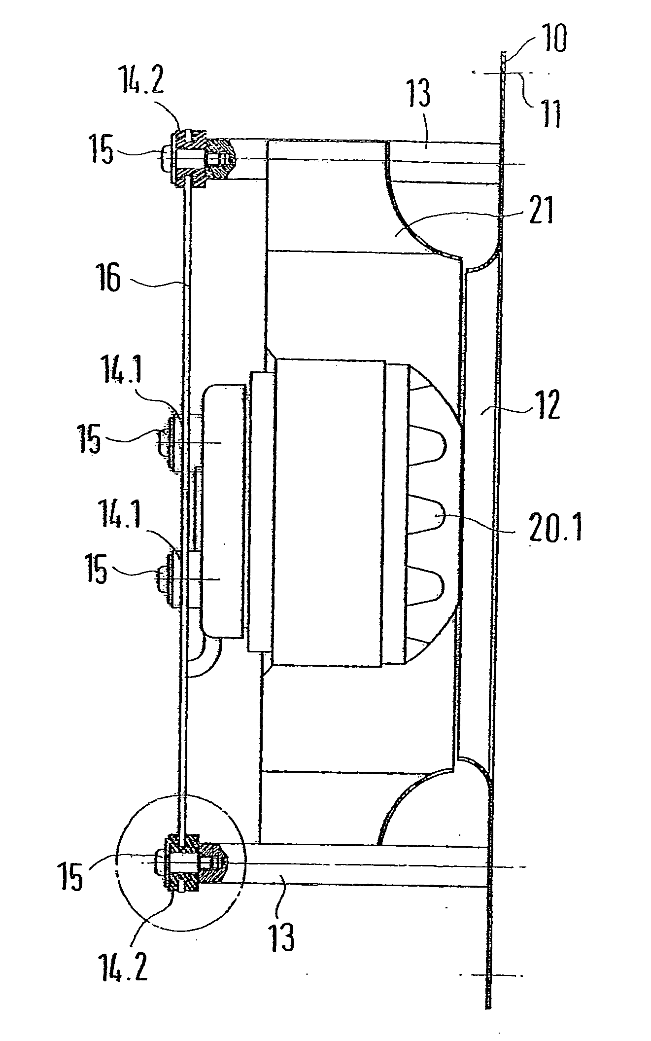
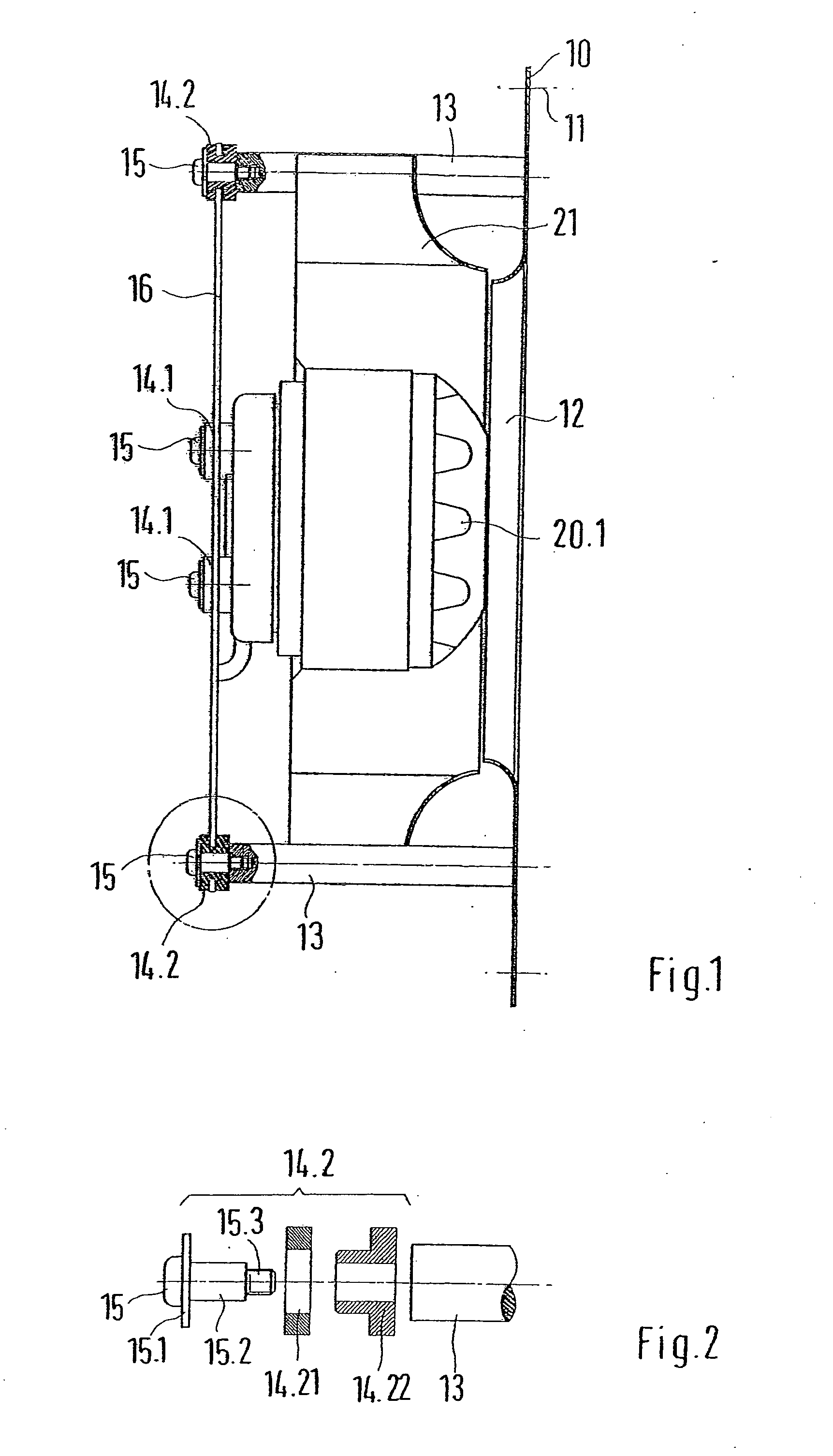
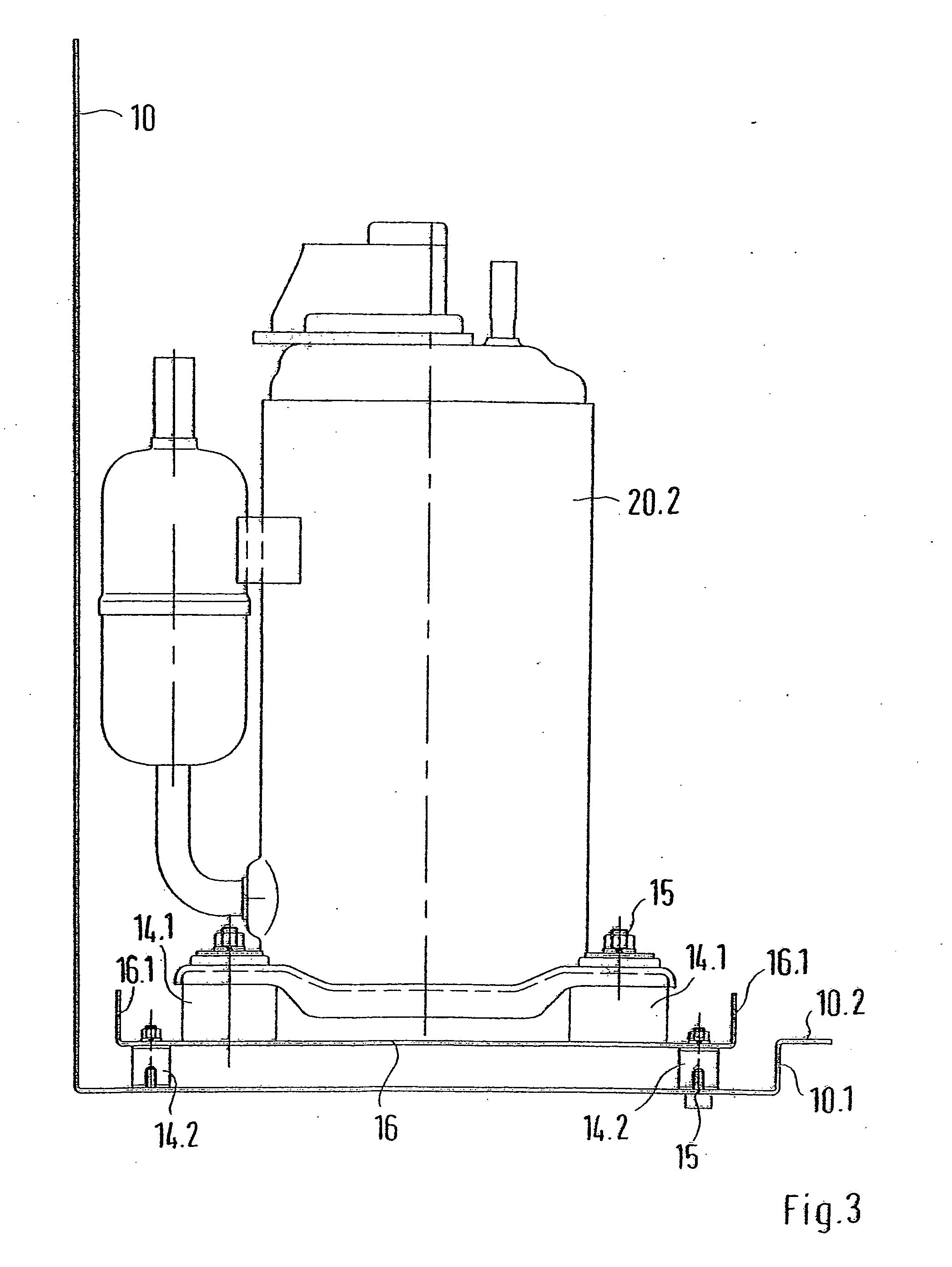
[0020] Portions of a cooling device are shown in the drawings, which can be attached to a housing receiving electrical installations, for example a switchgear cabinet. In turn, the switchgear cabinet can be attached to a machine tool. The cooling device has a refrigeration cycle system, in which coolant is conveyed. At least two fans 20.1 are part of the refrigeration cycle system, one of which is respectively assigned to an evaporator or a condenser of the refrigeration cycle system. The fan 20.1 is mounted via vibration dampers 14.1 on an intermediate bracket 16.1. The intermediate bracket 16.1 can be a sheet metal plate covering the back of the fan 20.1. The intermediate bracket 16.1 has bores along the edges, in which vibration dampers 14.2 can be mounted. The structure of the vibration dampers 14.2 are shown in greater detail in FIG. 2. As shown, the vibration damper 14.2 has a damping element 14.22, which has a cylindrical holding shoulder and a collar section of enlarged diam...


PUM


Abstract

A cooling device, in particular for a switchgear cabinet with a housing, in which a refrigeration cycle system is housed, wherein the refrigeration cycle system has vibration-generating elements, namely a compressor and at least one fan. The fan and the compressor are supported in the housing via vibration dampers. For preventing vibratory emissions a cooling device in accordance with this invention has the fan and/or the compressor separately supported by first vibration dampers on an intermediate bracket, or together on an intermediate bracket. The intermediate bracket is supported by second vibration dampers on a bracket, and the bracket is connected to the housing.

Description

BACKGROUND OF THE INVENTION [0001] 1. Field of the Invention [0002] This invention relates to a cooling device, in particular for a switchgear cabinet with a housing, in which a refrigeration cycle system is housed, wherein the refrigeration cycle system has vibration-generating elements, including a compressor and at least one fan, wherein the fan and the compressor are supported in the housing via vibration dampers. [0003] 2. Discussion of Related Art [0004] Cooling devices are known in the prior art. The refrigeration cycle system is formed by a compression refrigeration system having a compressor, an evaporator, a condenser, an expansion valve, pipelines and fans. The motors of the fans and of the compressor cause vibrations, which are transferred to the housing of the cooling device, and then to the connected switchgear cabinet. [0005] When the cooling device is installed on a machine tool, this can be disadvantageous, because the vibrations are then transmitted to the processi...

Claims


Application Information

Patent Timeline
Patent Type & Authority Applications(United States)
IPC IPC(8): F25D23/00
CPCF04B39/0044H05K7/20172F25D23/006F25B2500/13F25D19/00F24F5/00F25B31/00
Inventor IMMEL, MANFREDMAUL, JOACHIM
Owner RITTALWERK RUDOLF LOH GMBH & CO KG
Why Eureka
Try Eureka