
Method and system for dynamic compensation of bi-directional flow sensor during respiratory therapy

a flow sensor and dynamic compensation technology, applied in the field of clinical systems, can solve the problems of difficult to accurately measure the flow rate of expired breathing gas, time-consuming, and expensive, and achieve the effect of accurate gas flow in volume measurement and accurate identification of flow direction

Inactive Publication Date: 2008-02-07
GENERAL ELECTRIC CO
View PDF14 Cites 8 Cited by
  • Summary
  • Abstract
  • Description
  • Claims
  • Application Information

AI Technical Summary

Benefits of technology

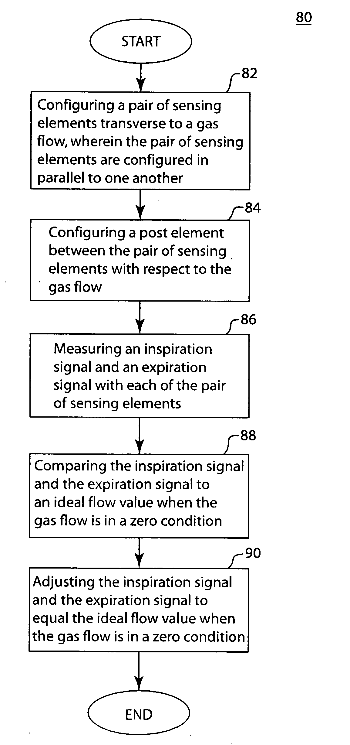
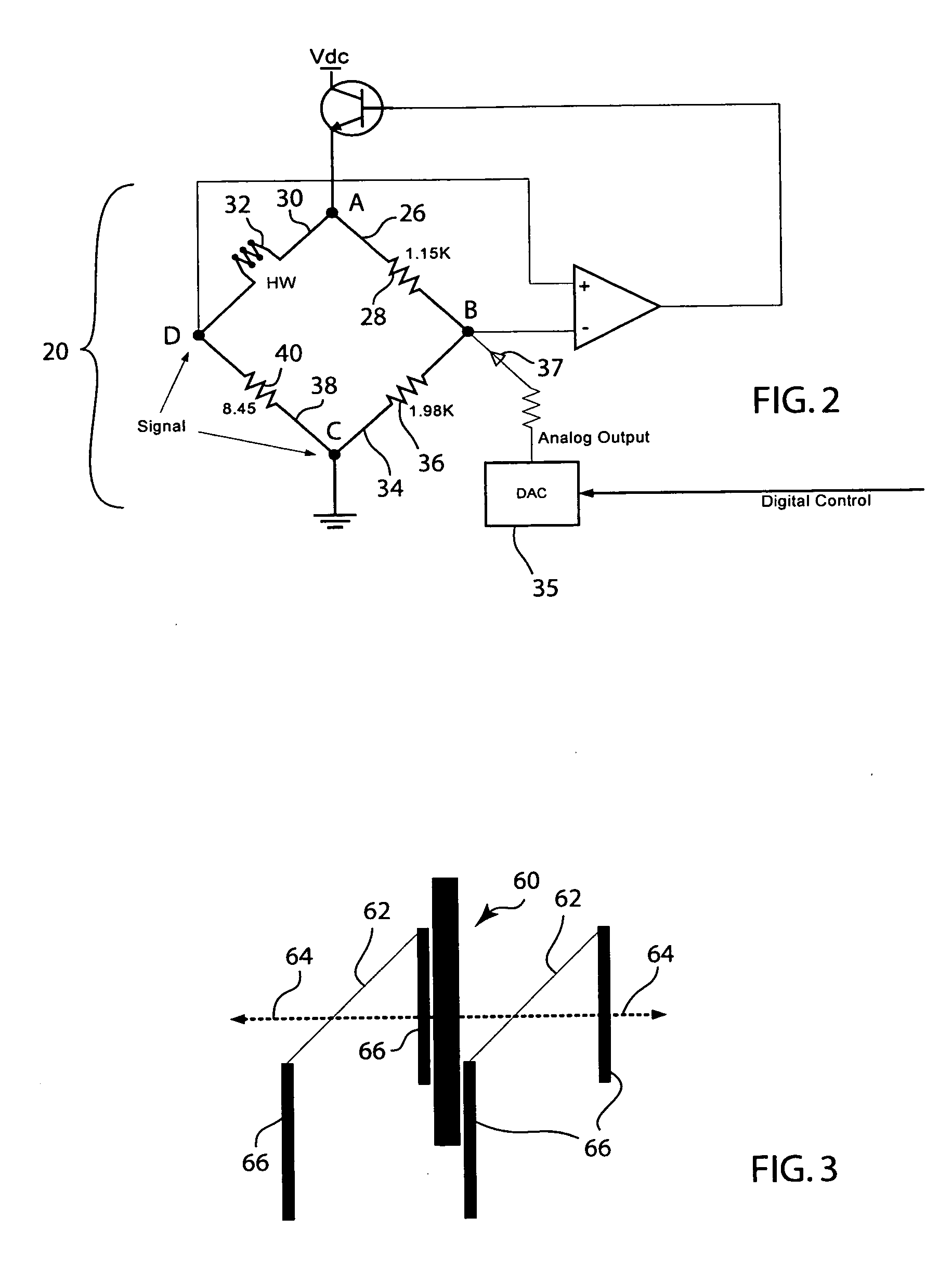
[0008]The method and system includes a flow sensor including two hot wire gas flow sensing elements connected to identical, but independent electronic circuitry, positioned in parallel, transverse to gas flow direction, and separated by a post that serves to shadow the downstream element. The flow sensors are dynamically compensated during respiratory therapy by use of digital to analog conversion, which provides for more accurate identification of flow direction and more accurate gas flow in volume measurements. The method and system incorporates the flow sensors in the y-piece of a breathing circuit.

Problems solved by technology

Measuring the flow rate of expired breathing gas is particularly difficult due to the wide range of instantaneous gas flow rates found during expiration, variations in the composition of the exhaled breathing gases, the moisture and sputum exhaled in the breathing gases, and for other reasons.
While highly suited as a means for measuring gas flow rates, certain problems have heretofore attended the use of hot wire anemometers.
One problem arises during replacement of the wire sensing resistor due to breakage or other reasons.
This requirement has rendered calibration of hot wire gas flow rate sensors when the sensing resistor is replaced as awkward, time consuming, and expensive.

Method used


Image

  • Method and system for dynamic compensation of bi-directional flow sensor during respiratory therapy
  • Method and system for dynamic compensation of bi-directional flow sensor during respiratory therapy
  • Method and system for dynamic compensation of bi-directional flow sensor during respiratory therapy

Examples


Embodiment Construction

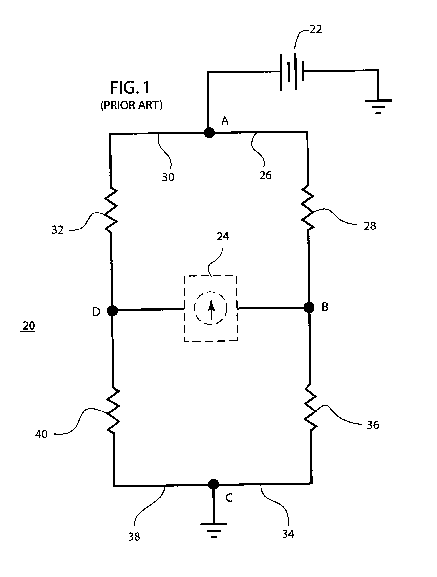
[0017]The construction and operating principles of a simple bridge circuit of the type employed in the sensor of the present invention are described below in connection with FIG. 1. The bridge circuit shown in FIG. 1 is commonly termed a Wheatstone bridge. Bridge circuit 20 has input terminals A and C connected to a voltage source 22 and a pair of output terminals B and D which may be connected to an output indicating device 24, such as a galvanometer. Bridge arm 26 extends between input terminal A and output terminal B and contains resistor 28. Bridge arm 30 extends between input terminal A and output terminal D and contains resistor 32. Bridge arm 34 extends between output terminal B and input terminal C and contains resistor 36. Bridge arm 38 extends between input terminal C and output terminal D and contains resistor 40.

[0018]The operation of bridge circuit 20 is as follows. Assume resistor 28 has a value of 100 ohms, resistor 36 has a value of 1,000 ohms, resistor 32 has a valu...


PUM


Abstract

The method and system includes a flow sensor including two hot wire gas flow sensing elements connected to identical, but independent electronic circuitry, positioned in parallel, transverse to gas flow direction, and separated by a post that serves to shadow the downstream element. The flow sensors are dynamically compensated during respiratory therapy by use of digital to analog conversion, which provides for more accurate identification of flow direction and more accurate gas flow in volume measurements. The method and system incorporates the flow sensors in the y-piece of a breathing circuit.

Description

FIELD OF THE INVENTION[0001]The invention relates to the field of clinical systems. More particularly, the invention relates to the field of life support solutions.BACKGROUND OF THE INVENTION[0002]The present invention relates to gas flow sensors employing a heated resistance wire, commonly called hot wire anemometers. Numerous applications require measurement of the flow rate of a gas or mixture of gases. One such application is in medical apparatus, such as ventilators, for measuring the flow rate of respiratory breathing gases expired by the subject. Measuring the flow rate of expired breathing gas is particularly difficult due to the wide range of instantaneous gas flow rates found during expiration, variations in the composition of the exhaled breathing gases, the moisture and sputum exhaled in the breathing gases, and for other reasons.[0003]Hot wire gas flow sensors, or anemometers, have found use as expiratory breathing gas flow sensors in ventilators and similar equipment. ...

Claims


Application Information

Patent Timeline
Patent Type & Authority Applications(United States)
IPC IPC(8): G01F7/00
CPCA61B5/0878G01F1/72G01F1/6842
Inventor CHRISTENSEN, DAVID ALLAN
Owner GENERAL ELECTRIC CO
Learn More